Chapter29 - Academic Program Pages at Evergreen
advertisement
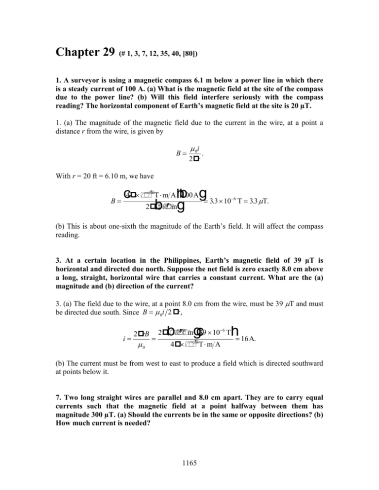
Chapter 29 (# 1, 3, 7, 12, 35, 40, [80]) 1. A surveyor is using a magnetic compass 6.1 m below a power line in which there is a steady current of 100 A. (a) What is the magnetic field at the site of the compass due to the power line? (b) Will this field interfere seriously with the compass reading? The horizontal component of Earth’s magnetic field at the site is 20 µT. 1. (a) The magnitude of the magnetic field due to the current in the wire, at a point a distance r from the wire, is given by B 0i 2r . With r = 20 ft = 6.10 m, we have c4 T m Ahb100 Ag 3.3 10 B 2 b mg 6 T 3.3 T. (b) This is about one-sixth the magnitude of the Earth’s field. It will affect the compass reading. 3. At a certain location in the Philippines, Earth’s magnetic field of 39 µT is horizontal and directed due north. Suppose the net field is zero exactly 8.0 cm above a long, straight, horizontal wire that carries a constant current. What are the (a) magnitude and (b) direction of the current? 3. (a) The field due to the wire, at a point 8.0 cm from the wire, must be 39 T and must be directed due south. Since B 0i 2 r , i 2 rB 0 b gc h 16 A. 2 m 39 106 T 4 T m A (b) The current must be from west to east to produce a field which is directed southward at points below it. 7. Two long straight wires are parallel and 8.0 cm apart. They are to carry equal currents such that the magnetic field at a point halfway between them has magnitude 300 µT. (a) Should the currents be in the same or opposite directions? (b) How much current is needed? 1165 1166 CHAPTER 29 7. (a) The currents must be opposite or antiparallel, so that the resulting fields are in the same direction in the region between the wires. If the currents are parallel, then the two fields are in opposite directions in the region between the wires. Since the currents are the same, the total field is zero along the line that runs halfway between the wires. (b) At a point halfway between they have the same magnitude, 0i/2r. Thus the total field at the midpoint has magnitude B = 0i/r and i prB 0 p 0.040 m 300 106 T 4p 10- 7 T m A 30 A. 12. Figure 29-42a shows, in cross section, two long, parallel wires carrying current and separated by distance L. The ratio i1/i2 of their currents is 4.00; the directions of the currents are not indicated. Figure 29-42b shows the y component By of their net magnetic field along the x axis to the right of wire 2. (a) At what value of x > 0 is By maximum? (b) If i2 = 3 mA, what is the value of that maximum? What is the direction (into or out of the page) of (c) i1 and (d) i2? 12. The fact that By = 0 at x = 10 cm implies the currents are in opposite directions. Thus By = o i1 o i2 o i2 4 1 – = L + x – x . 2(L + x) 2 x 2 using Eq. 29-4 and the fact that i1 = 4 i2. To get the maximum, we take the derivative with respect to x and set equal to zero. This leads to 3x2 – 2Lx – L2 = 0 which factors and becomes (3x + L)(x L) = 0, which has the physically acceptable solution: x = L . This produces the maximum By: o i2 /2L. To proceed further, we must determine L. Examination of the datum at x = 10 cm in Fig. 29-42(b) leads (using our expression above for By and setting that to zero) to L = 30 cm. (a) The maximum value of By occurs at x = L = 30 cm. (b) With i2 = 0.003 A we find o i2 /2L = 2.0 nT. (c) and (d) Fig. 29-42(b) shows that as we get very close to wire 2 (where its field strongly dominates over that of the more distant wire 1) By points along the –y direction. The right-hand rule leads us to conclude that wire 2’s current is consequently is into the page. We previously observed that the currents were in opposite directions, so wire 1’s current is out of the page. 35. Each of the eight conductors in Fig. 29-60 carries 2.0 A of current into or out of the page. Two paths are indicated for the line integral § B · ds. What is the value of the integral for (a) path 1 and (b) path 2? 1167 35. (a) Two of the currents are out of the page and one is into the page, so the net current enclosed by the path is 2.0 A, out of the page. Since the path is traversed in the clockwise sense, a current into the page is positive and a current out of the page is negative, as indicated by the right-hand rule associated with Ampere’s law. Thus, z B ds 0i 2.0 A 4 107 T m A 2.5 106 T m. b gc h (b) The net current enclosed by the path is zero (two currents are out of the page and two are into the page), so B ds 0ienc 0 . z 40. A solenoid that is 95.0 cm long has a radius of 2.00 cm and a winding of 1200 turns; it carries a current of 3.60 A. Calculate the magnitude of the magnetic field inside the solenoid. 40. It is possible (though tedious) to use Eq. 29-26 and evaluate the contributions (with the intent to sum them) of all 1200 loops to the field at, say, the center of the solenoid. This would make use of all the information given in the problem statement, but this is not the method that the student is expected to use here. Instead, Eq. 29-23 for the ideal solenoid (which does not make use of the coil radius) is the preferred method: B 0in 0i NI F G H J K where i = 3.60 A, 0.950 m and N = 1200. This yields B = 0.00571 T. OPTIONAL 80. In Fig. 29-65, an arrangement known as Helmholtz coils consists of two circular coaxial coils, each of N turns and radius R, separated by distance s. The two coils carry equal currents i in the same direction. (a) Show that the first derivative of the magnitude of the net magnetic field of the coils (d/B/dx) vanishes at the midpoint P regardless of the value of s. Why would you expect this to be true from symmetry? (b) Show that the second derivative (d2B/dx2) also vanishes at P, provided s = R. This accounts for the uniformity of B near P for this particular coil separation. 80. (a) The magnitude of the magnetic field on the axis of a circular loop, a distance z from the loop center, is given by Eq. 29-26: B N 0iR 2 , 2( R 2 z 2 ) 3/ 2 1168 CHAPTER 29 where R is the radius of the loop, N is the number of turns, and i is the current. Both of the loops in the problem have the same radius, the same number of turns, and carry the same current. The currents are in the same sense, and the fields they produce are in the same direction in the region between them. We place the origin at the center of the lefthand loop and let x be the coordinate of a point on the axis between the loops. To calculate the field of the left-hand loop, we set z = x in the equation above. The chosen point on the axis is a distance s – x from the center of the right-hand loop. To calculate the field it produces, we put z = s – x in the equation above. The total field at the point is therefore B L M N O P Q N 0iR 2 1 1 2 . 2 2 3/ 2 2 2 (R x ) ( R x 2 sx s2 ) 3/ 2 Its derivative with respect to x is L M N O P Q dB N 0iR 2 3x 3( x s) 2 . 2 2 5/ 2 dx 2 (R x ) ( R x 2 2 sx s2 ) 5/ 2 When this is evaluated for x = s/2 (the midpoint between the loops) the result is L M N O P Q dB N 0iR 2 3s / 2 3s / 2 2 2 0 2 2 5/ 2 dx s/ 2 2 ( R s / 4) ( R s / 4 s 2 s 2 ) 5/ 2 independent of the value of s. (b) The second derivative is L M N d 2 B N 0iR 2 3 15x 2 dx 2 2 ( R 2 x 2 ) 5/ 2 ( R 2 x 2 ) 7 / 2 3 15( x s) 2 ( R 2 x 2 2 sx s 2 ) 5/ 2 ( R 2 x 2 2 sx s 2 ) 7 / 2 O P Q At x = s/2, d 2B dx 2 s/2 N 0iR 2 6 30s 2 / 4 ( R 2 s 2 / 4)5/ 2 ( R 2 s 2 / 4)7 / 2 2 N 0 R 2 6( R 2 s 2 / 4) 30 s 2 / 4 s2 R2 2 3 N iR . 0 2 ( R 2 s 2 / 4)7 / 2 ( R 2 s 2 / 4)7 / 2 Clearly, this is zero if s = R.
