Appendix 1 Derivation of relationships for plane stress and plane
advertisement
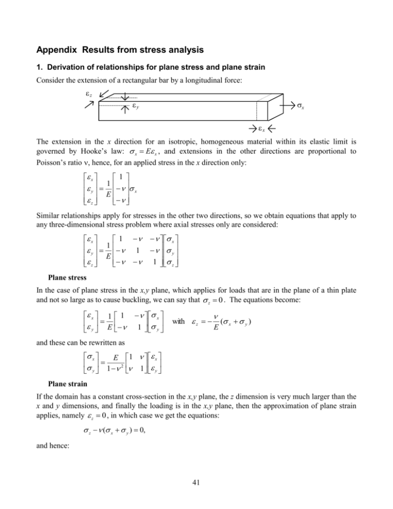
Appendix Results from stress analysis 1. Derivation of relationships for plane stress and plane strain Consider the extension of a rectangular bar by a longitudinal force: z y x x The extension in the x direction for an isotropic, homogeneous material within its elastic limit is governed by Hooke’s law: x E x , and extensions in the other directions are proportional to Poisson’s ratio , hence, for an applied stress in the x direction only: x 1 1 y E x z Similar relationships apply for stresses in the other two directions, so we obtain equations that apply to any three-dimensional stress problem where axial stresses only are considered: x 1 1 y E z 1 x y 1 z Plane stress In the case of plane stress in the x,y plane, which applies for loads that are in the plane of a thin plate and not so large as to cause buckling, we can say that z 0 . The equations become: x 1 1 y E x 1 y with z E ( x y ) and these can be rewritten as x E 2 y 1 1 x 1 y Plane strain If the domain has a constant cross-section in the x,y plane, the z dimension is very much larger than the x and y dimensions, and finally the loading is in the x,y plane, then the approximation of plane strain applies, namely z 0 , in which case we get the equations: z ( x y ) 0, and hence: 41 x 1 1 2 y E 2 z x 1 1 x E 1 y y x 1 1 y E 2 x 1 2 y 1 and finally: x x 1 E 1 y y 1 1 2 Addition of shear stress and strain If a pure shear stress xy (called simply for now) is applied in the x,y plane as shown: y x y' x' u v . We can show, using y x x applied in the directions, where y this will result in a shear strain xy (called for now), where xy Mohr’s circle, that this is precisely equivalent to stresses these axes are rotated 45° anticlockwise from the normal axes (i.e. 2=90°). The most straightforward way to derive a relationship between and is to use the strain energy, which must be equal when calculated for either pattern of stress. We have, by using the appropriate relations x x between and for either plane stress or for plane strain (which result in the same equations in y y this case): 2 1 (1 ) (1 ) W 12 12 12 12 E E E E . 2(1 ) When this is used with the relationships above, we obtain the stress-strain relations for the case of plane stress: If we now say that G , where G is the shear modulus, we obtain the expression G x E y 1 2 xy 1 0 x 0 0 0 0 1 0 0 0 0 0 E y 1 2 0 0 0 0 0 0 G xy 42 1 1 0 0 0 x 0 y 1 (1 ) xy 2 and for plane strain: x 1 E 1 y 1 1 2 xy 0 0 0 x 0 y 1 (1 2 ) xy 2 Equations may be derived in a similar manner for the full three-dimensional case, for axisymmetric analysis, and for other cases such as orthotropic materials, in which properties are constant on parallel planes in the material (and for which there are, for example, two values of E). 2. Principal stresses Stresses in two dimensions are described in terms of three components: x , y , xy , but the values of these depend on the choice of axes. That is, the three components aren’t really independent of each other. As illustrated above, a pure shear stress can be regarded as equivalent to longitudinal stresses along axes at 45° to the original ones. If material failure is to be considered, then the greatest possible values of tensile and shear stresses are likely to be important, and it is these that are contoured by FINEL. If axes are chosen at an appropriate angle, it can be shown that all three stress components can be expressed completely in terms of just two longitudinal stresses, either tensile or compressive or one of each. These are called the principal stresses. Since stress values vary throughout the domain, the appropriate angle also varies, so the principal stresses are calculated at each point in the domain, together with the angle at which they apply. (Note that, mathematically, this transformation is equivalent to finding principal moments of inertia, and to diagonalisation of matrices.) If the material failure is likely to be in tension, then it will be the most positive value of a principal stress that will determine failure; this is called the maximum principal stress. The least positive value, or most negative, is called the minimum principal stress. Note also that both may be positive (tension) or both negative (compression). If material failure is likely to be in shear, then a similar calculation can reveal the maximum shear stress. However, for plane strain or axisymmetric problems (where all calculations take place in two dimensions), the maximum shear stress may be in the third dimension; FINEL takes account of this in plotting contours of maximum shear stress. The calculation of values and angle for principal stresses is often done using ‘Mohr’s circle’, as follows: The three stress components x , y , xy are used to plot points on a diagram as shown: xy 2 y x min 43 max A semi-circle is then plotted centred at the mid-point between x , y and through the two ordinates. The two intersections of the circle with the x-axis then give the maximum principal stress and the minimum principal stress, and the angle gives the anticlockwise angle of the maximum principal stress direction from the original x-axis. Important note: There is a maximum and a minimum at every point in the domain; they are the extreme values attained at each point, not the extreme values for the whole domain. 3. Derivation of equilibrium equations in two dimensions To obtain the equlibrium equations, we consider a small element of material, with stresses acting on it: y + y x xy+ xy xy + xy y xy x xy x + x y In the x and y directions, the net forces acting must total zero, namely: xy xyx 0, yx xyy 0, x x y xy y x 0 x y y y x xy x y 0 y x and in the limit as x , y 0 , we obtain the equations: x xy 0, x y y y xy x 0 . Similarly, equilibrium equations may be obtained between stress components in the x,z plane and the y,z plane. 44

