modulation QPSK
advertisement
IMPROVING LEARNING EFFICIENCY FOR DIGITAL
MODULATION COURSES
Ph. DONDON- J.M MICOULEAU-P.KADIONIK
ENSEIRB, 1 avenue A. Schweitzer- 33402 TALENCE
FRANCE
Philippe.Dondon@enseirb.fr
Abstract : - Teaching the digital transmission techniques- like other fields of electronic- is not always easy : There
is classically theoretical courses and practical lessons. The link between the two is often the most important
difficulty that appears for the students. An abundant literature on digital wireless with a high level mathematical of
modelling is of course available. Since a few years, theoretical courses are easily illustrated by the 2D computer
simulations. But simple descriptions or analysis are rarely found and simulations do not replace a concrete true
design. In order to improve the efficiency of our teaching, we present here a practical and pedagogical approach
including practical electronic considerations, original and simple “Costas loop” description and design
considerations for understanding and designing communication circuits. Based on the psychological Hermann
brain model, this method looks like a progressive linear guide. A QPSK modulator/demodulator topology is used
to illustrate our approach.
1. Introduction
Since a few years, we observed some major
changes in student’s behaviour in our engineer
school: They are less interested in theory and
“reject” all courses which have no concrete
application. So, one of our challenge is how to
motivate these new students generation to the
fundamental courses. Moreover, even if simulations
tools like SIMULINK are helpful and “funny to
use”, they do not fit perfectly the behaviour of a true
circuit. The use of an intuitive and practical
approach seems to be more efficient than traditional
courses for these students. The job we present here
is a try to create a didactical link between theoretical
course and practical lesson. The example of a hand
made QPSK modulator/demodulator is used to
illustrate this approach.
3. QPSK modulation
3.1 QPSK Modulator design
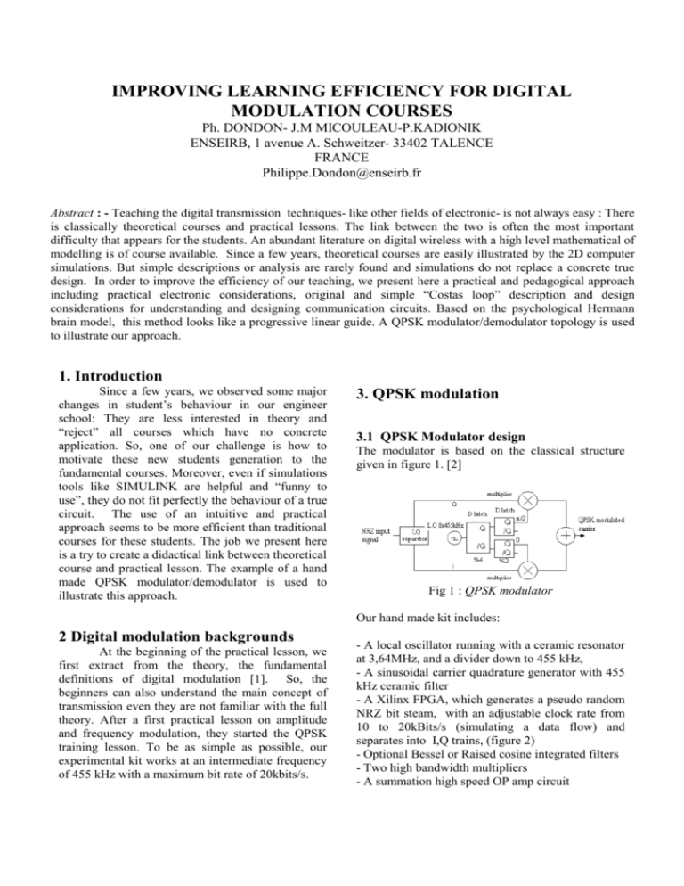
The modulator is based on the classical structure
given in figure 1. [2]
Fig 1 : QPSK modulator
Our hand made kit includes:
2 Digital modulation backgrounds
At the beginning of the practical lesson, we
first extract from the theory, the fundamental
definitions of digital modulation [1]. So, the
beginners can also understand the main concept of
transmission even they are not familiar with the full
theory. After a first practical lesson on amplitude
and frequency modulation, they started the QPSK
training lesson. To be as simple as possible, our
experimental kit works at an intermediate frequency
of 455 kHz with a maximum bit rate of 20kbits/s.
- A local oscillator running with a ceramic resonator
at 3,64MHz, and a divider down to 455 kHz,
- A sinusoidal carrier quadrature generator with 455
kHz ceramic filter
- A Xilinx FPGA, which generates a pseudo random
NRZ bit steam, with an adjustable clock rate from
10 to 20kBits/s (simulating a data flow) and
separates into I,Q trains, (figure 2)
- Optional Bessel or Raised cosine integrated filters
- Two high bandwidth multipliers
- A summation high speed OP amp circuit
Serial NRZ
in put
(FPGA)
-5V
6
S
5
D
3
CLK
H/2
R
Q
1
Q
2
4
-5V
U7:A
9
2
11
1
4013
-5V
8
U5:B
S
Q
13
Q
12
D
4069
10
U6:A
S
5
D
3
CLK
Q
1
Q
2
J2
I ouput
R
4
4013
-5V
I,Q separation
U7:B
U7:C
3
4
B
CLK
R
-5V
6
U5:A
4069
5
Fig 4 : Cosine raised filter response
J3
6
4069
Q output
4013
-5V
Fig 2 : I,Q data generator schematic
Thus, the impact of filtering on modulated
carrier spectrum and eye diagram can be easily
observed (cf section 5). The I, Q data’s can also be
(or not) synchronised with the carrier just to make
the observation of modulated signal easier.
I and Q are generated inside the FPGA : the figure 3
illustrates the timing diagram according to figure 2
schematic: from the NRZ signal, one bit over two is
switched to the I output, and one over two is
switched to the Q output. The I,Q data rate is thus
half of the clock rate. [6]
Fig 5 : modulator block diagram
3.2 QPSK Demodulator design
The demodulator is based on the classical
coherent demodulator structure given in figure 6.
Fig 3 : I, Q separation diagram
Upper trace: NRZ incoming signal
Middle traces: I and Q separated trains
Lower trace: NRZ data clock
Due to the power supply circuit, I and Q are two
levels bipolar signals with an average DC voltage
equal to zero. So, I and Q can be symbolically
represented by two level values +1 and -1.
On our kit, I and Q arms can be (or not) filtered by
an improved Bessel 8th order LT 1164-7 [5] or
LT1069-7 raised cosine filter (which are close
enough to Gaussian filters) as indicated on block
diagram in Figure 5. The figure 4 gives the
theoretical response of a raised cosine filter where
is called the roll off factor.
Fig 6 : QPSK Costas loop demodulator
Our hand made demodulator kit includes:
-A voltage controlled oscillator at 4 x 455 kHz and a
divider down to 455 kHz,
- A sinusoidal carrier quadrature generator with 455
kHz ceramic filter
- Two analogue multipliers for coherent
demodulation
- Two simple low pass filters (I, Q filtering)
- Two fast comparators for sign detection
- Two analogue multipliers, a error OP amp circuit,
and a first order loop filter for the Costas loop.
Even if the Costas loop is well known and
classically used in the most digital transmission
since almost 40 years, only highly strong
mathematical analysis are available to understand
the operating mode of this loop.
Between the too much theoretical approach
and the too much simple explanations and synoptic
we founded in the literature, we developed a quite
simple approach to help the students in that way.
The incoming signal can be written as:
Ve(t) = I cost +Q sint , where is the
carrier frequency.
Let suppose that the local oscillator (Vol) of
the receiver is locked on the carrier frequency but
not exactly in phase.
Thus, we can say: Vol = A cos(t+).
To understand the impact of , we have to
make a simple trigonometric calculus.
At the multiplier output of the “I arm”, we obtain:
A cos(t+ ).[ I cost +Q sint]
After low pass filtering on the “I arm”:
A.I/2 .cos – A.Q/2 .sin
At the multiplier output of the “Q arm”, we obtain:
A sin(t+ ).[ I cost +Q sint]
After low pass filtering on the “Q arm”:
-A.I/2 .sin + A.Q/2 .cos
Assuming small, and using limited development
formulas, it yields:
For the I arm and from (1) :
A/2.I (cos - Q/I. tg )
Thus:
A/2.I (1--(Q/I).)
For the Q arm and from (2)
A/2.Q(cos + I/Q. tg )
Thus:
A/2.Q(1- + I/Q. )
After crossed multiplication between one arm by the
sign of the other, the error voltage Vd can be written
as :
Vd={sign (arm I) x arm Q} - {sign (arm Q) x arm I}
I
+1
-1
+1
-1
Q
-1
+1
+1
-1
Error voltage Vd
A/2. [-I.(1+- Q.(1-]
A/2. [+I.(1++ Q. .(1-]
A/2.[I.(1--Q.(1+]
A/2.[-I.(1-+Q.(1+]
Table 2
After replacing I and Q by there values (+1,-1) in
each expression, it yields:
Vd= A/2.(-2.) whatever the symbol value
The error voltage Vd is thus always,
proportional to the phase shift while remains small
(between –/4 et +/4). In fact, we can show that
Vd=f() is a /2 periodic function. The loop can be
locked with a phase ambiguity of k. /2. Confusion
or inversion on I and Q bits can then occur. This
well known phenomenon can be visualized on our
practical kit.
From this shortened analysis, we can understand
some basic effects of a non zero phase shift:
- When increases, we can guess, from table 1, a
change in the amplitude of I and Q : a confusion
between the logical level ‘1’ et ‘0’ can occur.
- These changes can also be simulated using Excel
or “Matlab Simulink” software, for example.
- At least, the effect of the phase shift can be
observed looking at the I,Q constellation :
introduces a rotation compared to the ideal position.
Then, the amplitude changes can also be
interpreted by comparing the vector projection on I
and Q axis. (cf figure 7)
(3)
Q
10
11
I
(4)
As we can see on (3) and (4), I and Q are
fully well recognised if equal zero.(case of perfect
coherent demodulation).
00
01
Fig 7 : effect of phase shift
The Costas loop description is finished like a
classical PLL loop with a loop filter and VCO.
Replacing the feed back loop by an equivalent phase
comparator, the analogue loop filter characteristics
are “guessed” by the students according to VCO
lock and capture range and to the equivalent phase
comparator gain: a low pass structure including an
integrator cell is at least required to ensure a null
phase error.
In order to characterize the loop behaviour as simply
as possible, we add on our demodulator card, some
extra functionalities as indicated in figure 8.
recognised method is intended for better
including/understanding the preferences of an
individual like his approach to particular problems.
It results in a representation of the brain into four
quadrants (figure 9) which correspond to four
preferences of operation. Quadrant A (blue) shows
the preference of the individual for logic, modelling,
(typical profile : mathematician, data processing
specialist …)B (green) its aptitude for the practice
and planning (real time production scheduler,
administrative profile…). The quadrant D (yellow)
shows the preference for the risk and projection in
the future (typical profile : "start-up" manager, risk
manager, artist…), and C (red) for the relational
one, emotion (typical profile : social and
commercial workers.
Left brain Right brain
abstraction,
logical
Abstraction
One way left
sollicitation
Rigour
Right brain
sollicitation
omitted
Imagination
Feeling,
intuition
Fig 8 : demodulator block diagram
Planification,
concrete
emotion
Concrete
Fig. 9 : Herman brain model
- a programmable delay line allows to enter directly
the carrier reference from the modulator (instead of
the local recovery carrier) and delays it, in order to
obtain the transfer curve Vd=f(). It can also be
used to observe the impact of on I and Q arms, eye
and constellation diagram. (Cf section 5)
- an “open loop switch” allows to characterize the
static and dynamic VCO and loop filter behaviours.
3.3 Electronic design considerations
We spontaneously designed our QPSK kit using
classical discrete components instead of fully
integrated ones. This allows a better understanding
of the individual functionalities and a full test and
characterization of each block included in the
design.
We can also use the Herman model to improve the
teaching approach: indeed, if one superimposes the
traditional diagrams of teaching scientists (course,
training, practical lesson) on the diagram, one
realises that the process of training requests only the
left brain, that the approach is downward (theory
towards the practice or practical towards the theory).
Consequently, the motivation, the emotional aspect,
the need to know with what is useful received
teaching, is completely ignored. This negligence
partly results in reinforcing the incomprehension of
the pupils, their lack of interest and their
absenteeism.
Left brain Right brain
Abstraction
4. Teaching strategy
Rigour
Imagination
4.1 Hermann model short description
Ned Hermann, past manager of the formation at
General electric company developed a technique
making it possible to easily know the cerebral
preferences of an individual. This universally
Concrete
Fig. 10 : optimal use of brain capacities
According to Hermann conclusion, the best way to
optimize the motivation of our students is to sweep
all the quadrants starting from the right parts during
an integrated lesson. (figure 10)
4.2 Applying Hermann model
As said previously, the most important for the
students is to link the theory of digital modulation to
a practical design as simply as possible:
The theoretical classical course on digital
communications is chained with the practical
training as soon as possible to maximize the
efficiency of teaching.
According to the Hermann model the four
quadrant of the brain model are swept, starting with
the right C quadrant. And the practical lesson looks
like a linear progressive tutorial guide with
important “mile stones” :
a) Analysis of schematic diagram: (interactive work
with the teacher) (“C” and “D” quadrant
solicitation)
- Functional analysis
- Electrical analysis
- Validation of Components choices,
- Main components data sheet readings
- Effect of current and voltage static offset
of the integrated circuits,
- Signal level choices and dynamic range
justification,
-Pseudo random generator analysis (clock,
NRZ, I and Q signal observation (analog/digital
mixed oscilloscope)
- Impact of the clock rate and of the random
sequence length on the NRZ spectrum.
(Oscilloscope FFT)
b) Test of the QPSK modulator : (individual
student’s work) (“B” quadrant solicitation)
-Local quadrature oscillator frequency and
distortion measurement (oscilloscope, time and
FFT)
-QPSK modulated signal observation (time
and frequency domain, spectrum analyser)
-I,Q eye diagram (constellation analyser) [5]
-Bessel and cosine filter characterization
(frequency and time responses drawings)
-Effect of I,Q filtering (secondary lobe
suppression, spectrum analyser)
-Effect of the bit rate on useful bandwidth
(manual sweep of the data clock, spectrum analyser)
c) Test of the demodulator: (individual student’s
work)
-Transfer curve Vd=f() drawing ( using the
programmable integrated delay line, and a DC
voltmeter)
-Effect of carrier phase shift on I, Q.
Visualization of the constellation rotation. (Delay
line and X,Y oscilloscope)
-Open loop test (lock range adjustment)
-Open loop gain transfer curve drawing
-Loop filter cut off frequency determination
(graphical method)
-Closed loop test
-Constellation and eye diagram observation
when locked (oscilloscope)
d) Test of modulator/demodulator (individual
student’s work) (“B” quadrant solicitation)
-Phase
ambiguity
carrier
recovery
observation. (Powering on and off the power supply)
-Costas loop lock range measurement.
(Manual frequency sweep of the modulator carrier)
- Frequency and phase locking ability after a
cut of modulator/demodulator connection.
-I,Q demodulated stream observation
e) Results debriefing (interactive work with the
teacher) (“A” quadrant solicitation)
Then, this lesson can be (or not) followed by an
other one’s, much more detailed, depending on the
optional courses chosen by students (in the third
year school). A vector signal analyser is then used
for refining and completing measurements like jitter,
phase error, and other complex parameters like bit
error rate.
5. Experimental
As example, we give some experimental results
obtained during this practical lesson. The figure 11
shows the initial modulated signal spectrum without
filtering. And figure 10 shows the effect of I,Q
Bessel filtering with a cut-off frequency half of the
bit rate :
- Reduction of useful bandwidth to the main
lobe (secondary lobes suppression)
-Proportionality between bit rate (20 kbits/s
here) and the main lobe width (20kHz). (center
frequency 459kHz)
The figure 14 shows the effect of a phase shift on
the constellation according to the theoretical figure
7: Using the external carrier input and varying the
delay time with micro switches, the constellation
can be rotated up to around 45°.
Fig 11 : Modulated carrier spectrum without I,Q
filtering
Fig 14: QPSK constellation rotation
Fig 12 : modulated carrier spectrum with I,Q Bessel
filtering
The figure 15 shows the eye diagram in case of
perfect coherent demodulation (when Costas loop
locked). (Tektronix oscilloscope in “trace memory”
mode). The eye’s shape and aperture depends also
on the I,Q filter choice. Here, we used an improved
Bessel filter with a cut-off frequency of 9,2kHz (the
half of the bit rate). The thickness of the trace is due
to residual signal at twice the carrier frequency
(910kHz).
The figure 13 shows the constellation diagram
obtained after demodulation when the costas loop is
locked (Using a Tektronix oscilloscope in XY
mode). The shape of the transitions between the four
QPSK points depends on the I,Q filters type.
Without any filter, only the four points would
appear.
Fig 15: eye diagram
Finally, a picture of our hand made QPSK
modulator/demodulator boards and test equipment is
given in figure 16.
Fig 13 : QPSK constellation
[7] Hikmet Sari, Transmissions des signaux
numériques, E-7100, vol E, Techniques de
l’ingénieur, Paris
Fig 15 : QPSK test bench
6. Conclusion
This paper is a digest of our integrated
pedagogical approach. The link between theory and
practical lessons has been exposed. A more detailed
paper is obviously given to our engineer students.
this full integrated approach is now used in our
engineer school to teach the digital circuit’s
application and design. As we can see since a few
years, the classical and conventional teaching
method reached their limits. Including psychological
aspects, we have shown that it is possible to
improve the efficiency of our teaching.
Even if it is always difficult to “measure”
the impact of a teaching strategy, this one seems to
be more attractive and efficient than before, looking
at the results of annual “student satisfaction report”:
The last one shows that the satisfaction rate raised
from 45% up to 65%. One other important point is
that the students stay until they finish all the lesson
even it is late: they do not leave anymore before the
end, like before. This is an encouraging sign of a
true motivation for this practical approach.
Of course, these first improvements will
have to be obviously confirmed in the future.
References :
[1] J. Proakis, Digital communications, Fourth
Edition, Mc Graw Hill, 2001.
[2] F. de Dieuleveult, Electronique appliquée aux
hautes fréquences, éd DUNOD Paris 1999
[3] B. Escrig, Cours systèmes de communications
numériques, ENSEIRB 2003
[4] LT 1164-7 application note 56 January 1994
[5] Agilent Vector signal analysis basics application
note 150-15
[6] Ph. Dondon, Cours interne de faisceaux
hertziens numériques, T.R.T. company , 1989

