Chapter 2. Basic formulation of Continuum Mechanics
Chapter 2 .
Basic formulation of Continuum Mechanics & Theory of Elasticity
Sample problems
2-S1
What is the relationship between the internal energy of an elastic solid and the elastic constants?
Solution to 2-S1
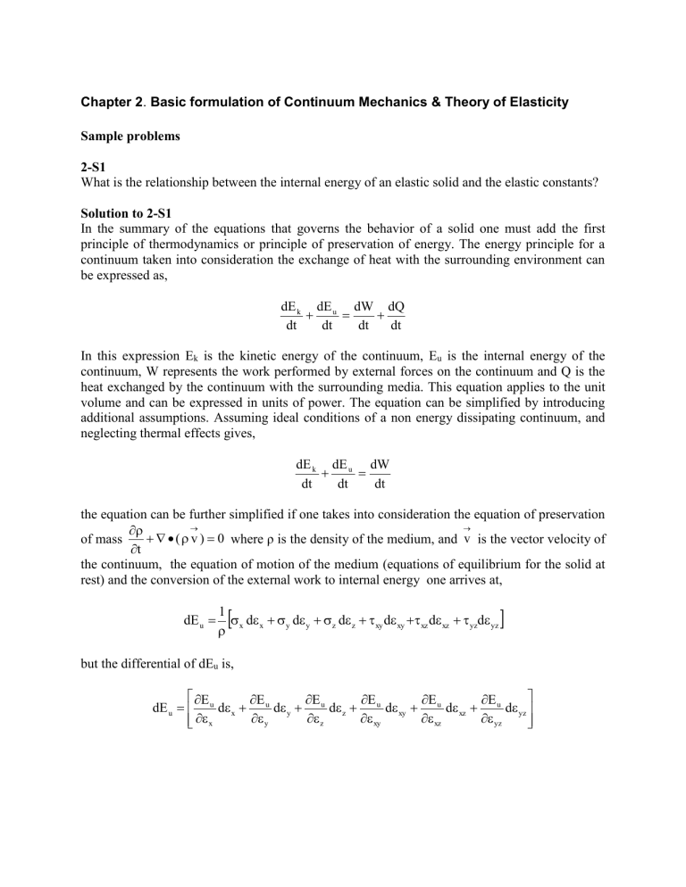
In the summary of the equations that governs the behavior of a solid one must add the first principle of thermodynamics or principle of preservation of energy. The energy principle for a continuum taken into consideration the exchange of heat with the surrounding environment can be expressed as, dE k dt
dE u dt
dW dt
dQ dt
In this expression E k
is the kinetic energy of the continuum, E u
is the internal energy of the continuum, W represents the work performed by external forces on the continuum and Q is the heat exchanged by the continuum with the surrounding media. This equation applies to the unit volume and can be expressed in units of power. The equation can be simplified by introducing additional assumptions. Assuming ideal conditions of a non energy dissipating continuum, and neglecting thermal effects gives, dE k dt
dE u dt
dW dt the equation can be further simplified if one takes into consideration the equation of preservation of mass
t
(
v )
0 where ρ is the density of the medium, and
v is the vector velocity of the continuum, the equation of motion of the medium (equations of equilibrium for the solid at rest) and the conversion of the external work to internal energy one arrives at, dE u
1
x d
x
y d
y
z d
z
xy d
xy
xz d
xz
yz d
yz
but the differential of dE u
is, dE u
E
x u d
x
E u
y d
y
E
z u d
z
E u
xy d
xy
E u
xz d
xz
E u
yz d
yz
From the two above equations one gets equations of the form,
x
E u
x
and similar equations for all the other components. If the medium is a linearly isotropic elastic material the expression of the energy density becomes utilizing the principal stresses
E u
1
2 E
(
1
2
3
)
2
2 ( 1
)(
1
2
2
3
3
1
)
As a function of the principal strains,
E u
E
2 (
)( 1
2
)
( 1
2
)(
2
1
2
2
2
3
)
(
1
2
3
)
2
The expression of the density of elastic energy for an elastic material is a quadratic expression on the stresses or on the strains. Consequently the assumption that the material is linearly elastic is equivalent to assume that internal energy density is a quadratic function of the stresses or strains.
2-S2
Consider the Airy’s function Φ=Cr θ sin θ where r and θ are polar coordinates in 2-D. To this function corresponds the stresses (2.49),
r
2 C cos
,
r
0
,
r
(a)
Utilize this solution to obtain the elastic state of stresses of the problem shown in Figure P2.3.
Solution to 2-S2
Let us consider a plate as shown in Figure P2.1 loaded in the upper edge by loads normal to the boundary at a distance M very large compared to the segment AB the effects of the loads will be small. Under those conditions the plate can be considered as semi-infinite.
Figure P2.1. Plate with loads applied to the edges
Figure P.2.2 shows the coordinate system selected to formulate the problem of the stress sate produced by applying a concentrated load P at a point 0 of the boundary. Taking the angle θ positive in the clock direction
Figure P2.2. Semi-infinite plate with a concentrated load P applied to the edge
The boundary conditions are,
0 for
2
,
r
0 , for
2
and also
r
0 These conditions are satisfied by the stresses given by equations (a). It is possible to see that for the radial stress at r=0 the stress
r
. This is a singularity of the elastic solution that must be removed. An usual procedure to remove the singularity is to consider a semi-circle of radius Δr,
Figure P2.2 (b), then we can write,
r
2 C
r cos
. Assuming that the thickness of the plate t=1we compute the resultant force for an element of arc, (b)
r r
2 C cos
d
. We can now consider the equilibrium of the forces, recalling that P is the applied force the static equilibrium conditions are that the resulting reaction forces of the plate must be such that P=V, the vertical component,
H=0 where H is the horizontal component. The vertical component of the forces given by (b) are, dV
2 C cos
2 d
and dH
2 C cos
sin
d
.If we integrate the preceding equations,
V
2 C
2
2
cos
2 d
C
and H
2 C
2
2
cos
sin
d
0 . Then P
C
0 and finally
C=P/π. Then the solution of the problem is,
r
2 P r
cos
,
0 ,
r
0
Through Saint-Venant it is known that the state of stresses at a certain distance from the point of application of the concentrated force will be given by the above solution. Since a point force cannot physically exist in reality forces are applied through contact stresses. If the contact region is very small and the applied force is big enough, the material cannot remain in the elastic state and a transition region will exist in the region of application of the force. Figure P2.3 shows a plot of the state of stresses of the semi-infinite plate with a concentrate line load, the theoretical
distribution resulting from the solution that has been obtained in this problem. Since the state of stresses reduces to one single principal stress σ r
, the lines representing the level of stress are circles and at the same time are isochromatics, isopachics, and lines of equal pressure. a) b)
Figure P2.3.Semi-infinite plate loaded with concentrated line load.(A.J Durelli) a)Theoretical solution for a line load applied to the boundary b) Experimental results obtained utilizing Photoelasticity that agree well with the theoretical
One can see at least qualitatively in Figure P2.3 that the experimental results match the theoretical solution. One can also see in this figure the value of σ r
along the line of action of the force.
Problems to be solved
2-1
For an isotropic elastic material obtain the expression of the elastic energy density utilizing the
Lamé constants and the stress tensor.
2-2
For an isotropic elastic material obtain the expression of the elastic strain density as a function of the Lamé constant and the strain tensor.
2-3
If one selects displacements as the more convenient unknowns to solve an elasticity problem, if a point of the boundary is prescribed to undergo given displacements:
What will the boundary conditions be at this particular point?
2-4
If one finds out that to solve a given elastic problem the selection of the stress components as unknowns is the best choice: How are you going to formulate the boundary conditions in terms of stresses?
2-5
An aluminum plate, E = 78.6 GPa and G = 29.65 GPa is subjected to a bi-dimensional field, the stress tensor is
0 x
0
y
The values of the principal stresses can be varied but the strain energy level should be kept constant at 104 KPa.
Compute the maximum value of σ x that can preserve the strain energy level.
Hint: Work with the energy density expression for the plate.
2-6
The simply supported beam in Figure P2.4 has a span and a rectangular cross-section of depth
2a and thickness h. The beam has two reactions R
A and R
B
that can be computed from the 2-D static conditions of equilibrium. These reactions can be considered as forces distributed at both ends of the beam. Actually this hypothesis is not correct however according to the Saint-Venant principle the effect of this assumption will be negligible at a distance of each end equal 2a, the depth of the beam.
Figure P2.4. Simply supported beam with a linear load.
Formulate the boundary conditions following the approach applied in Section 2.6. Show that the state of stresses is given by the 6 degree polynomial
p
2
4 a
3
1
6 x
3 y
3
1
10 yx
5
1
2 a
2 y
3 x
a
2
5
2
6
yx
3
a
2 2
2 a
4
10
yx
a
3
3 y
3
Show that the stresses satisfy the boundary conditions.
2-7
Derive the Cartesian equations corresponding to the solution of sample problem 2S2 .
Hint: Convert polar components to Cartesian components
2-8
Obtain the expression of the state of stresses of the semi-infinite plane seen in Figure P2.5.
Figure P2.5. Semi-infinite plane loaded with a uniform load in a region of the boundary
Hint: Utilizing the results of sample problem 2S2 and applying the superposition principle of solution of the theory of elasticity obtain the expression for the state of stresses of the plate.
2-9
A plastic pipe is embedded in a wall that has a modulus of elasticity E
P
<<E
W
. As a good approximation one can consider the pipe embedded on a rigid medium and subjected to internal pressure.
Figure P2.6.Long pipe embedded in a rigid wall
Compute the stresses and displacements in the pipe.
The ratio r o
/r i
=2.5 and Poisson’s ratio ν=0.33.
Hint: Since the boundary conditions correspond to displacements the solution should be attempted utilizing displacements (see (2.58)).
