III. Test results
advertisement
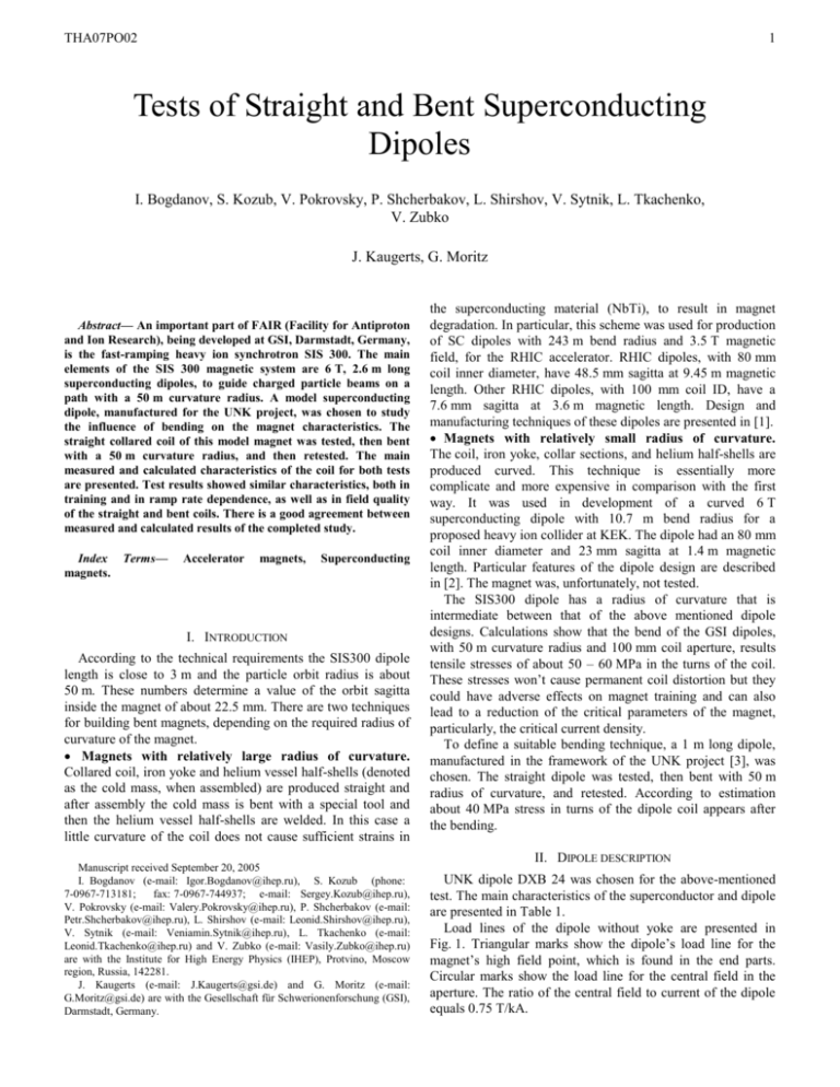
THA07PO02 1 Tests of Straight and Bent Superconducting Dipoles I. Bogdanov, S. Kozub, V. Pokrovsky, P. Shcherbakov, L. Shirshov, V. Sytnik, L. Tkachenko, V. Zubko J. Kaugerts, G. Moritz Abstract— An important part of FAIR (Facility for Antiproton and Ion Research), being developed at GSI, Darmstadt, Germany, is the fast-ramping heavy ion synchrotron SIS 300. The main elements of the SIS 300 magnetic system are 6 T, 2.6 m long superconducting dipoles, to guide charged particle beams on a path with a 50 m curvature radius. A model superconducting dipole, manufactured for the UNK project, was chosen to study the influence of bending on the magnet characteristics. The straight collared coil of this model magnet was tested, then bent with a 50 m curvature radius, and then retested. The main measured and calculated characteristics of the coil for both tests are presented. Test results showed similar characteristics, both in training and in ramp rate dependence, as well as in field quality of the straight and bent coils. There is a good agreement between measured and calculated results of the completed study. Index Terms— magnets. Accelerator magnets, Superconducting I. INTRODUCTION According to the technical requirements the SIS300 dipole length is close to 3 m and the particle orbit radius is about 50 m. These numbers determine a value of the orbit sagitta inside the magnet of about 22.5 mm. There are two techniques for building bent magnets, depending on the required radius of curvature of the magnet. Magnets with relatively large radius of curvature. Collared coil, iron yoke and helium vessel half-shells (denoted as the cold mass, when assembled) are produced straight and after assembly the cold mass is bent with a special tool and then the helium vessel half-shells are welded. In this case a little curvature of the coil does not cause sufficient strains in Manuscript received September 20, 2005 I. Bogdanov (e-mail: Igor.Bogdanov@ihep.ru), S. Kozub (phone: 7-0967-713181; fax: 7-0967-744937; e-mail: Sergey.Kozub@ihep.ru), V. Pokrovsky (e-mail: Valery.Pokrovsky@ihep.ru), P. Shcherbakov (e-mail: Petr.Shcherbakov@ihep.ru), L. Shirshov (e-mail: Leonid.Shirshov@ihep.ru), V. Sytnik (e-mail: Veniamin.Sytnik@ihep.ru), L. Tkachenko (e-mail: Leonid.Tkachenko@ihep.ru) and V. Zubko (e-mail: Vasily.Zubko@ihep.ru) are with the Institute for High Energy Physics (IHEP), Protvino, Moscow region, Russia, 142281. J. Kaugerts (e-mail: J.Kaugerts@gsi.de) and G. Moritz (e-mail: G.Moritz@gsi.de) are with the Gesellschaft für Schwerionenforschung (GSI), Darmstadt, Germany. the superconducting material (NbTi), to result in magnet degradation. In particular, this scheme was used for production of SC dipoles with 243 m bend radius and 3.5 T magnetic field, for the RHIC accelerator. RHIC dipoles, with 80 mm coil inner diameter, have 48.5 mm sagitta at 9.45 m magnetic length. Other RHIC dipoles, with 100 mm coil ID, have a 7.6 mm sagitta at 3.6 m magnetic length. Design and manufacturing techniques of these dipoles are presented in [1]. Magnets with relatively small radius of curvature. The coil, iron yoke, collar sections, and helium half-shells are produced curved. This technique is essentially more complicate and more expensive in comparison with the first way. It was used in development of a curved 6 T superconducting dipole with 10.7 m bend radius for a proposed heavy ion collider at KEK. The dipole had an 80 mm coil inner diameter and 23 mm sagitta at 1.4 m magnetic length. Particular features of the dipole design are described in [2]. The magnet was, unfortunately, not tested. The SIS300 dipole has a radius of curvature that is intermediate between that of the above mentioned dipole designs. Calculations show that the bend of the GSI dipoles, with 50 m curvature radius and 100 mm coil aperture, results tensile stresses of about 50 – 60 MPa in the turns of the coil. These stresses won’t cause permanent coil distortion but they could have adverse effects on magnet training and can also lead to a reduction of the critical parameters of the magnet, particularly, the critical current density. To define a suitable bending technique, a 1 m long dipole, manufactured in the framework of the UNK project [3], was chosen. The straight dipole was tested, then bent with 50 m radius of curvature, and retested. According to estimation about 40 MPa stress in turns of the dipole coil appears after the bending. II. DIPOLE DESCRIPTION UNK dipole DXB 24 was chosen for the above-mentioned test. The main characteristics of the superconductor and dipole are presented in Table 1. Load lines of the dipole without yoke are presented in Fig. 1. Triangular marks show the dipole’s load line for the magnet’s high field point, which is found in the end parts. Circular marks show the load line for the central field in the aperture. The ratio of the central field to current of the dipole equals 0.75 T/kA. THA07PO02 2 NbTi 50±4 copper 0.85 6 0.42±0.02 (1.39±0.1)/1 10±2 ≥ 70 600±50 2.5±0.2 oxide 19 0.984 III. TEST RESULTS A. Training and Ramp Rate Dependence The behavior of the dipole training before and after bending is shown in Fig. 2. After bending, the dipole began to retrain. The maximum critical current reached during training of the dipole did not decrease after its bending. 7.5 7.4 5.5 11 10 9 Current (kA) 8 SC cable critical current Central load line Load line of end parts 7 6 5 Quench current (kA) 7.3 4 5.4 7.2 7.1 5.3 7.0 5.2 6.9 5.1 6.8 5.0 6.7 6.6 Straight Bent 6.5 3 4.9 4.8 6.4 2 0 1 0 0.0 0.5 1.0 1.5 2.0 2.5 3.0 3.5 4.0 4.5 5.0 5.5 6.0 6.5 7.0 4 6 8 10 12 14 16 18 20 Quench sequence Fig. 2. Magnet training before and after bending. Magnetic field (T) Quench current (kA) Fig. 1. Load lines of dipole without iron yoke. The square marked line shows dependence of the critical current on magnetic field for superconducting wire with 600 A critical current at B = 5 T and T = 4.23 K. This critical current corresponds to 2.5 kA/mm2 critical current density. The dipole, manufactured from this superconducting wire, can reach 5.3 T central magnetic field at 7.2 kA current. The superconducting cable has electrical insulation, consisting of two layers of 20 μm thick polyimide film and one layer of 100 μm thick fiberglass tape, impregnated with epoxy. The superconducting coil was cured at a temperature of 150° C for 2 hours. It was noticed that there were stress drops in both layers of the magnet coil due to creep, during long time of magnet storage. Therefore, the dipole was reassembled before testing. An additional 0.1 mm thick spacer was inserted at the median plane of the coil. In addition the insulation, which is placed on the outside of the outer layer, was increased by 60 μm. After assembly, the mechanical preloads consisted of 100 MPa and 80 MPa in the inner and outer layers, respectively. The dipole was bent by clamps in a special frame which supplied the bending of the dipole during test. The coil resistance before bending was 0.4456 . Coil 2 Central field (T) Superconducting alloy Titanium percentage, % Matrix material Wire diameter, mm Filament diameter, μm Filling factor Copper to non-copper area ratio Twist pitch, mm Residual Resistance Ratio (RRR) of matrix Critical current at B = 5 T, T = 4.23 K, A Critical current density at B = 5 T, T = 4.23 K, kA/mm2 Wire coating Cable strand number Transfer function with iron yoke, T/kA resistance after bending was 0.4462 . Insulation resistance before and after bending is more than 3 G. Resistances of the coil and ground insulation of straight and bent dipoles were equal, showing an absence of turn-to-turn shorts. The measured values of RRR for this dipole, before and after bending, were 55. 7.46 7.44 7.42 7.40 7.38 7.36 7.34 7.32 7.30 7.28 7.26 7.24 7.22 5.54 5.52 5.50 5.48 5.46 5.44 Bent I Bent II Straight I Straight II 0 5.42 Central field (T) TABLE I CHARACTERISTICS OF DXB 24 SUPERCONDUCTING DIPOLE 5.40 5.38 100 200 300 400 500 600 700 800 900 1000 Current ramp rate dI/dt (A/s) Fig. 3. Ramp rate dependences of the straight and bent dipoles before (I) and after (II) 1000 cycles of 0 – 5 T – 0 with 1000-A/s current ramp rate. Fig. 3 presents ramp rate dependences for straight and bent dipoles, measured before (I) and after (II) 1000 cycles (0 – 5 T – 0 with 1000 A/s current ramp rate). From 0 to 1000 A/s (0.75 T/s) ramp rate value the critical current drop for the bent dipole are 72 A (0.97 %) before cycling and 55 A (0.74 %) after cycling. These values for the straight dipole are 112 A (1.53 %) before cycling and 47 A (0.64 %) after cycling. So, THA07PO02 3 the critical current drop, up to 0.75 T/s ramp rate, was not increased after the dipole bending and 1000 cycles. Field ramp rate (T/s) 0.0 Transfer function (T/kA) Total losses (J/magnet) 0.756 0.3 0.4 0.5 0.6 0.7 140 120 100 300 400 500 600 700 80 60 40 20 0.755 0 0.754 100 200 800 Current ramp rate (A/s) Fig. 6. Total losses in the dipole with iron yoke. 0.753 Field ramp rate dB/dt (T/s) 0.752 220 0.0 Central field (T) Nonlinearities bn (10 ) Fig. 4. Transfer function of the dipole at input and output of current. 1 0 -1 -2 -3 -4 -5 -6 -7 -8 b2 b4 -9 -10 b6 b2 straight -11 0.0 0.5 1.0 1.5 2.0 2.5 3.0 3.5 4.0 4.5 5.0 Central field (T) Fig. 5. Harmonics b2, b4 and b6 in the bent dipole. C. AC Losses Fig. 6 presents total losses in the UNK dipole DXB 24 (550 mm longitudinal length of the iron yoke) in 0 – 5T – 0 cycles with various magnetic field ramp rates measured in 1992. Straight and bend dipoles were tested without iron yoke and had practically equal AC loss values, which were higher by a factor of 1.3 than the losses in the dipole with iron yoke. Fig. 7 shows total losses in the bent dipole. Losses in magnet (J) 180 0.0 0.5 1.0 1.5 2.0 2.5 3.0 3.5 4.0 4.5 5.0 0.1 0.2 0.5 kA 2.0 kA 4.0 kA 6.0 kA 200 0.751 -4 0.2 500 A 1000 A 2000 A 3000 A 4000 A 5000 A 160 B. Magnetic Field Multipoles The dipole transfer function is presented in Fig. 4. The behavior of lower field multipoles of the bent dipole, shown in Fig. 5, coincides with harmonics for the straight dipole except for the larger value of b2, which is generated by dipole bending. This value should be taken into account during development of correction systems. 0.1 160 0.3 0.4 0.5 0.6 0.7 1.0 kA 3.0 kA 5.0 kA 6.7 kA 140 120 100 80 60 40 20 0 0 100 200 300 400 500 600 700 800 900 1000 Current ramp rate dI/dt (A/s) Fig. 7. Measured total losses in the bent dipole without iron yoke. For analysis of AC losses in the dipoles, dependence of the magnetization current density JCm for 6 m filaments in the strand versus magnetic field was used [4]. The best fit for this dependence is given by formula JCm= J0B0 /(B+B0), where J0 = 4.2671010 A/m2 and B0 = 0.251 T. The next generalized field dependence for determination of effective transverse resistivity of the matrix ef has been obtained from a large set of superconducting wire samples with 10 and 6 m diameter of filaments in the form of: ef = (a + bB)10-10 m. Parameters a = 4 and b = 1.3 give minimal matrix losses and a = 2 and b = 0.65 determine maximum values. Dependences of hysteresis losses on central field are presented in Fig. 8 for the straight and bent dipole as well as for the dipole with iron. Hysteresis losses in the dipole with iron were fitted by a parabolic function. The parabolic fit gives more accurate results at the level of higher currents (>3 kA). THA07PO02 4 Field distributions and operating currents in the dipoles with and without iron are different. Fig. 8 demonstrates practical coincidence of hysteresis losses with the accuracy limits of the measuring method. Fig. 8. Hysteresis losses in the dipoles. Time-dependent losses at 0.79 T/s (J) Dependences of time-dependent losses on central field are shown in Fig. 9 for the straight and bent dipoles and dipole with iron. Losses were recalculated at dB/dt = 0.79 T/s. It is seen the losses were not changed after dipole bending, but they became essentially larger in comparison with losses in the dipole with iron, which can be explained by the decreasing of Rc as the dipole turns were under high pressure at room temperature without motion during 12 years. 140 The main results of dipole test before and after magnet bending are the following: 1. Bending of the collared dipole coil (50 m curvature radius) did not produce turn-to-turn shorts and did not decrease ground insulation resistance. 2. The dipole begun to train afresh after the bending. Characteristics of training and ramp rate dependence of the straight and bent dipoles are similar. 3. The critical current of the dipole did not decrease after the bending which caused about 40 MPa stress in turns of the dipole. 4. 1000 cycles (0 – 5 T – 0 with 0.75 T/s magnetic field ramp rate) practically did not influence the critical current value and ramp rate dependence in the bent dipole. 5. Cable losses had increased after a storage period of twelve years as the coil turns were under high pressure at room temperature without motion. 6. AC losses were practically unchanged, after dipole bending. 7. Harmonic b2 was increased by dipole bending. This value should be taken into account during development of correction systems. REFERENCES [1] [2] 180 160 IV. CONCLUSION Straight dipole Bent dipole Dipole with iron [3] 120 [4] 100 80 60 40 20 0 0.0 0.5 1.0 1.5 2.0 2.5 3.0 3.5 4.0 4.5 5.0 Central field (T) Fig. 9. Time-dependent losses in the dipoles. D. Magnet Cycling The dipole was exposed to cycles of 0.5 – 6.8 – 0.5 - 6.8 s, that correspond to pause – ascent – plateau – descent. The corresponding field cycle was 0 – 5.0 – 0 T with 0.75 T/s field ramp rate or 1 kA/s, which was the maximum possible current ramp rate for the power supply. So, the total number of cycles was more than 1000. Quenches were not observed during magnet cycling and the critical current of the dipole did not decrease after this cycling. M. Andrella et al., “The RHIC magnet system,” Nuclear instruments and Methods in Physical Research, A 499, pp. 280-315, 2003. T. Shintomi et al., “Development of curved superconducting dipole magnet for Proton Synchrotron at KEK,” KEK Preprint 95-73, A, Jun. 1995. A. I. Ageyev, N. I. Andreev, I. V. Bogdanov et al., “Performance of UNK Superconducting Dipoles with Natural Oxide Coating of Strands”, IEEE Transactions on Applied Superconductivity, vol. 14, no. 2, pp. 263-266, Jun. 2004. A. N. Baidakov, K. P. Myznikov, L. S. Shirshov et al., “Study of the current carrying element of the superconducting dipole magnet for the UNK,” in Proc. of MT-11, Tsukuba, Japan, 1988, pp. 102-106.
