Applied Physics Letters
advertisement
Electron Velocity of 6×107 cm/s at 300 K in Stress Engineered InAlN/GaN Nano-Channel High-Electron-Mobility Transistors
Supporting Data
1
2
Source Resistance :
3
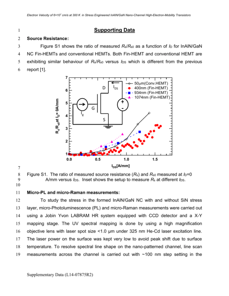
Figure S1 shows the ratio of measured Rs/Rs0 as a function of ID for InAlN/GaN
4
NC Fin-HEMTs and conventional HEMTs. Both Fin-HEMT and conventional HEMT are
5
exhibiting similar behaviour of Rs/Rs0 versus IDS which is different from the previous
6
report [1].
7
D
Rs/Rs0at ID= 0A/mm
6
50m(Conv.HEMT)
400nm (Fin-HEMT)
934nm (Fin-HEMT)
1074nm (Fin-HEMT)
IDS
5
4
Ig
G
S
3
2
1
0.0
0.5
1.0
1.5
IDS[A/mm]
7
8
9
10
Figure S1. The ratio of measured source resistance (Rs) and Rs0 measured at ID=0
A/mm versus IDS. Inset shows the setup to measure Rs at different IDS.
11
Micro-PL and micro-Raman measurements:
12
To study the stress in the formed InAlN/GaN NC with and without SiN stress
13
layer, micro-Photoluminescence (PL) and micro-Raman measurements were carried out
14
using a Jobin Yvon LABRAM HR system equipped with CCD detector and a X-Y
15
mapping stage. The UV spectral mapping is done by using a high magnification
16
objective lens with laser spot size <1.0 µm under 325 nm He-Cd laser excitation line.
17
The laser power on the surface was kept very low to avoid peak shift due to surface
18
temperature. To resolve spectral line shape on the nano-patterned channel, line scan
19
measurements across the channel is carried out with ~100 nm step setting in the
Supplementary Data (L14-07875R2)
Electron Velocity of 6×107 cm/s at 300 K in Stress Engineered InAlN/GaN Nano-Channel High-Electron-Mobility Transistors
1
scanner. Raman spectra are recorded from the patterned channel to check variation in
2
line shapes of optical phonon peaks.
3
4
Line-scan of micro-PL measurements:
5
The micro-PL (µPL) spectrum of the patterned nano-channel (NC) without SiN
6
passivation layer indicates the nature of the near-band-edge PL shifts when NC is
7
completely surrounded by the SiN layer (See Figure S2). The room temperature PL
8
spectra show a dominant near-band edge transition with a line shape broadening
9
toward the low energy side. The improved PL intensity observed from the top of NC is
10
attributed to the reduction of surface defect density and extraction of strong PL by light
11
scattering from the sidewalls of the NC (patterned region). The intensity is lower in the
12
mesa etched region due to plasma induced damage and point defects formation. The
13
increased intensity from the surface of the HEMT stack from patterned region helps to
14
distinguish the formed NC from the mesa etched region.
30x10
(a)
E~16.5 meV
50x10
(b)
20
InAlN/GaN w/o SiN
3.400
Energy [eV]
25
3.395
3
3.405
InAlN/GaN with SiN
PL Intensity [a.u.]
Energy [eV]
3.400
3
3.395
3.390
15
3.385
10
3.380
5
3.380
0
3.375
40
E~2.7 meV
30
3.390
20
3.385
~30900
PL Intensity [a.u.]
3.405
10
~25478
3.375
1
2
3
Position[m]
4
0
1
2
3
Position[m]
4
15
16
17
18
Figure S2. Micro-PL line-scan results from the InAlN/GaN NC (a) with and (b) without
SiN passivation.
19
The peak shift of about 16.5 meV is clearly seen in the micro-PL line scan of SiN
20
passivated NC region as seen from this Fig. S2. We have carried out repeated line
21
scans and we observed about ~10 meV additional peak shift of the SiN covered NC with
Supplementary Data (L14-07875R2)
Electron Velocity of 6×107 cm/s at 300 K in Stress Engineered InAlN/GaN Nano-Channel High-Electron-Mobility Transistors
1
respect to the SiN covered conventional HEMT surface. Therefore, based on the PL
2
peak shift vs. in-plane stress relationship, an additional in-plane stress component of
3
about 0.47 ± 0.02 GPa can be estimated. Similarly, red-shift was also reported in
4
AlGaN/GaN HEMT structure with SiN passivation [2]. The NC with additional in-plane
5
tensile stress can also produce polarized charges at the side walls that can lead to the
6
increase of 2DEG carrier density. There is a huge increase in the current density in the
7
InAlN/GaN NC Fin-HEMT observed in our experiment {See Figure 2(a) and (b)}.
8
Therefore, beside the contribution of in-plane stress in the channel region, the increased
9
carrier density could also be due to a modified band bending at the InAlN/GaN NC
10
sidewalls covered with SiN and the creation of positive charges at these SiN/InAlN/GaN
11
NC interfaces may lead to higher current density as compared to conventional planar
12
InAlN/GaN HEMTs. The decrease of sheet resistance with the increase of tensile stress
13
was also realized on InAlN/GaN nano-ribbon by finite element models [3]. The stress
14
under the T-gate regions {see regions (i) and (ii) in Fig 1(c)} can be even higher than the
15
regions {see inset of Fig 4(b)} subjected by micro-PL measurements. The stresses
16
under the T-gate regions are difficult to measure using optical techniques. Due to the
17
resolution limit of spectrometer in UV-Raman, the accuracy of estimated stress
18
component is lower than the estimated stress component by line-scanned micro-PL
19
(0.47±0.02 GPa) which offers a higher spectral resolution map {see Fig 4(a) and (b)}.
20
Therefore, more experimental studies needed to address the observations in such Fin-
21
HEMTs.
22
23
24
25
References
[1] D.S.Lee, H.Wang, A.Wu, M.Azize, O.Laboutin, Y.Cao, J.W.Johnson, E.Beam,
A.Ketterson, M.L.Schuette et al., IEEE Electron Device Lett., 34, 969 (2013).
26
[2] C.M.Jeon and A.-L.Lee, Appl. Phys. Lett., 86, 172101 (2005).
27
[3] E.J.Jones, M.Azize, M.J.Smith, T.Palacios and S.Gradecak, Appl. Phys. Lett.,
28
101, 113101 (2012).
Supplementary Data (L14-07875R2)


