A_6_2_1_4_Wind_Model
advertisement

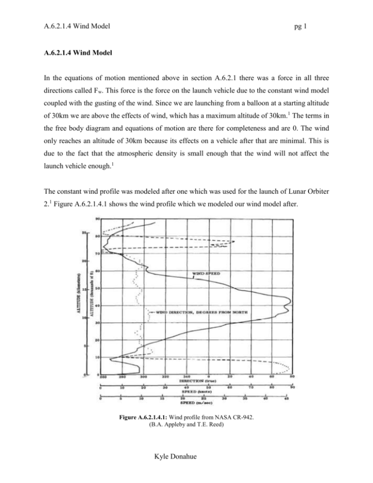
A.6.2.1.4 Wind Model pg 1 A.6.2.1.4 Wind Model In the equations of motion mentioned above in section A.6.2.1 there was a force in all three directions called Fw. This force is the force on the launch vehicle due to the constant wind model coupled with the gusting of the wind. Since we are launching from a balloon at a starting altitude of 30km we are above the effects of wind, which has a maximum altitude of 30km.1 The terms in the free body diagram and equations of motion are there for completeness and are 0. The wind only reaches an altitude of 30km because its effects on a vehicle after that are minimal. This is due to the fact that the atmospheric density is small enough that the wind will not affect the launch vehicle enough.1 The constant wind profile was modeled after one which was used for the launch of Lunar Orbiter 2.1 Figure A.6.2.1.4.1 shows the wind profile which we modeled our wind model after. Figure A.6.2.1.4.1: Wind profile from NASA CR-942. (B.A. Appleby and T.E. Reed) Kyle Donahue A.6.2.1.4 Wind Model pg 2 The dark solid line in the figure is the constant wind profile which we used for our model. We did not model the direction from NASA CR-942, we only used fig. A.6.2.4.1.1 for the speed of the constant wind. Figure A.6.2.1.4.2 is the constant wind profile we used in the trajectory and D&C models. Figure A.6.2.1.4.2: Constant Wind Profile for Project Bellerphone. (Kyle Donahue) Our wind model is a simplified version of one of the current models. We assume that the wind speed is related to altitude in a linear fashion. This is not the case but for our model the linear representation works very well. In creating the wind profile there had to be several assumptions made. The first assumption we made was that the constant wind is linear at different heights. Another assumption we make is that the constant wind will always be traveling in an easterly direction. This means that the wind can never go east to west. For example the constant wind profile is limited to angles greater than 0o and less than 180o on a compass. We also assumed there would be random wind gusts throughout the wind profile. The restriction on the wind gusts is that their direction can only be ±90o from the constant wind profile. Also the wind gusts will be seen as impulsive. The final Kyle Donahue A.6.2.1.4 Wind Model pg 3 assumption we made in creating the wind model is that the wind itself is only 2-D. We assume the wind will only be traveling in the north-east-south-west directions and never in the “up” or “down” directions. The constant wind profile is found using Matlab code AAE450_Wind_Model.m. For the initial analysis for Project Bellerphone the wind model was not used. Once some of the designs were not used and the amount of designs getting analyzed further decreased the wind model was implemented into the trajectory code. The wind model is broken up into several parts. The first part is computing the constant wind profile. The second part is determining the wind gusts. And the third part is converting the speed of the wind into the wind force (Fw). The first part of the wind model is coming up with the constant wind profile. The constant wind profile itself is made up of 2 parts; the direction and the speed. The first part of the code determines the speed of the wind. The code uses logic and information which is based on fig. A.6.2.1.4.1. The next step is determining the direction in which the constant wind profile is directed. Since the constant wind profile is launch dependent it will change every time the code is used. This works best as it represents the real wind profile more accurately. The third and final part of the wind model is converting the wind velocity, constant wind profile plus wind gusts, into the wind force which is used in the equations of motion. The equation we used for converting the wind velocity into wind force is using Eq. A.6.2.1.4.1 F w 1 2 W S w 2 Eq. A.6.2.1.4.1 Where Fw is the force of the wind, ρ is the density of the air at the particular altitude, W is the total wind velocity which is the constant plus the gust, and Sw is the area exposed to the wind at the given time. The force of the wind was model this way because we determined the wind would be a drag force. This is correct except at some times the wind will actually be helping but that is taken care of in the unit vector basis which was described earlier. Kyle Donahue A.6.2.1.4 Wind Model pg 4 The force of the wind on the launch vehicle was analyzed for all three body-fixed directions, br, bθ, and bφ. Since one of our assumptions was that the wind would never moving “up” or “down” the speed and force in the br is therefore 0. It was also analyzed for all altitudes starting with 0 and up till 30km. Figure A.6.2.1.4.3 is the wind force in the north/south direction, and fig. A.6.2.1.4.4 is the wind force in the east/west direction. Figure A.6.2.1.4.3: Force of the wind in the North/South compass direction. (Kyle Donahue) Kyle Donahue A.6.2.1.4 Wind Model pg 5 Figure A.6.2.1.4.4: Force of the wind in the East/West compass direction. (Kyle Donahue) Figure A.6.2.1.4.3 and fig. A.6.2.1.4.4 are examples of what the wind force could be. Since the wind is a random occurrence fig. A.6.2.1.4.3 and fig. A.6.2.1.4.4 will change each time. The two figures above have the constant wind profile and the wind gusts combined into one to create the wind vector which is used to create the wind force. Reference: 1 Appleby, B.A. and Reed, T.E., “Dynamic Stability of Space Vehicles,” NASA CR-942, November 1967. Kyle Donahue


