Supplementary materials: W-state Analyzer and Multi
advertisement
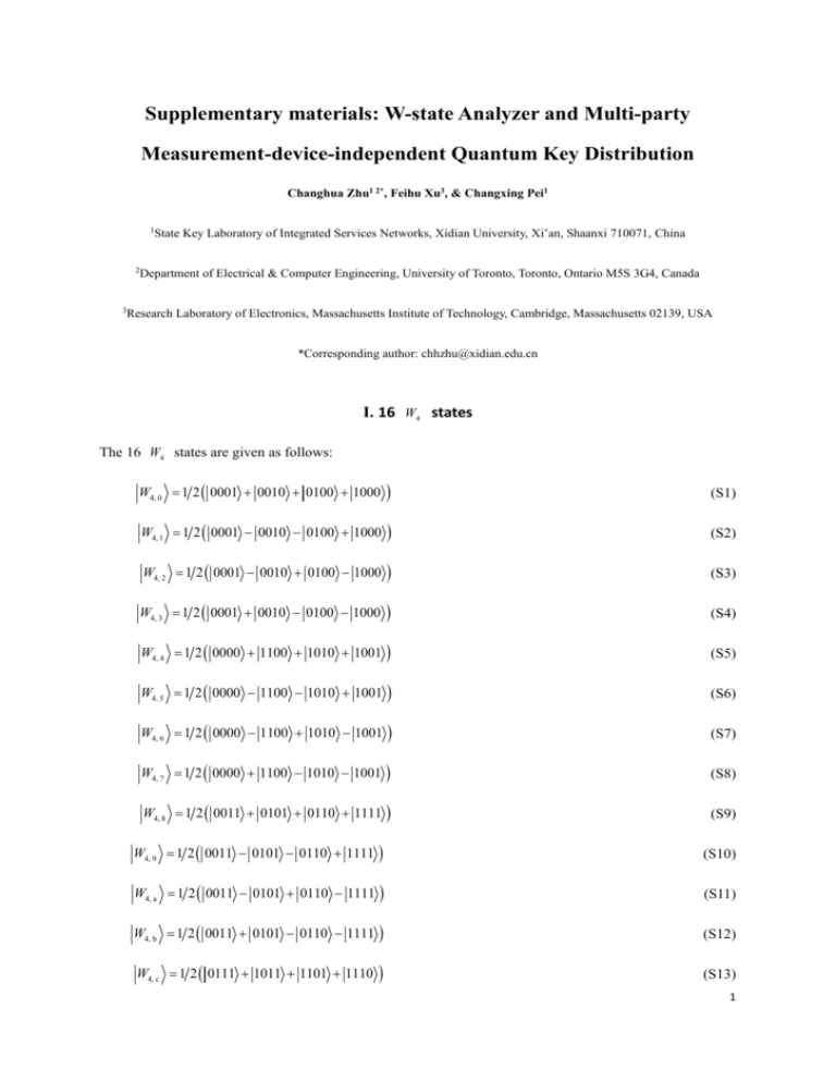
Supplementary materials: W-state Analyzer and Multi-party Measurement-device-independent Quantum Key Distribution Changhua Zhu1 2*, Feihu Xu3, & Changxing Pei1 1State Key Laboratory of Integrated Services Networks, Xidian University, Xi’an, Shaanxi 710071, China 2Department 3Research of Electrical & Computer Engineering, University of Toronto, Toronto, Ontario M5S 3G4, Canada Laboratory of Electronics, Massachusetts Institute of Technology, Cambridge, Massachusetts 02139, USA *Corresponding author: chhzhu@xidian.edu.cn I. 16 W4 states The 16 W4 states are given as follows: W4, 0 1 2 0001 0010 0100 1000 (S1) W4, 1 1 2 0001 0010 0100 1000 (S2) W4, 2 1 2 0001 0010 0100 1000 (S3) W4, 3 1 2 0001 0010 0100 1000 (S4) W4, 4 1 2 0000 1100 1010 1001 (S5) W4, 5 1 2 0000 1100 1010 1001 (S6) W4, 6 1 2 0000 1100 1010 1001 (S7) W4, 7 1 2 0000 1100 1010 1001 (S8) W4, 8 1 2 0011 0101 0110 1111 (S9) W4, 9 1 2 0011 0101 0110 1111 (S10) W4, a 1 2 0011 0101 0110 1111 (S11) W4, b 1 2 0011 0101 0110 1111 (S12) W4, c 1 2 0111 1011 1101 1110 (S13) 1 W4, d 1 2 0111 1011 1101 1110 (S14) W4, e 1 2 0111 1011 1101 1110 (S15) W4, f 1 2 0111 1011 1101 1110 (S16) The state W4, 0 given by equation (S1) is a standard W4 state and belongs to one family states The states W4, 1 , W4, 2 defined in Ref. 1. and W4, 3 can be constructed by performing unitary operations IZZI , ZIZI and ZZII on state W4, 0 , respectively, where I is the unit operator and Z is the Pauli Z operator. The states W4, c , W4, d , W4, e and W4, f XXXX operations on the states W4, 0 , W4, 1 , W4, 2 X operator. The state W4, 4 0 1 0 0 0 0 0 0 U 0 0 0 0 0 0 0 0 1 0 0 0 0 0 0 0 0 0 0 0 0 0 0 0 0 0 0 0 0 0 0 0 0 1 0 0 0 0 0 0 0 0 1 0 0 0 0 0 0 0 0 0 0 0 0 0 0 0 0 0 0 0 0 0 0 0 1 0 0 0 0 0 0 0 0 1 0 0 0 0 0 0 0 0 0 0 0 0 0 0 0 0 1 0 0 0 0 0 0 0 0 0 0 0 and W4, 3 , respectively, where X is the Pauli can be obtained by performing unitary operation U 0 0 0 0 0 1 0 0 0 0 0 0 0 0 0 0 0 0 0 0 0 0 0 0 0 0 0 0 1 0 0 0 0 0 0 0 0 0 1 0 0 0 0 0 0 0 0 0 0 0 0 0 0 0 0 1 0 0 0 0 0 0 0 0 0 0 0 0 0 0 0 0 1 0 0 0 0 0 0 0 0 0 0 0 0 0 0 0 0 0 0 1 0 0 0 0 0 0 0 0 0 0 0 0 0 0 0 0 0 1 0 0 on W4, 0 . The states W4, 5 , W4, 6 and W4, 7 0 0 0 0 0 0 0 0 0 0 0 0 0 0 1 0 0 0 0 0 0 0 0 0 0 0 0 0 0 0 0 1 can be obtained by performing ZIIZ , ZIZI and ZZII operations on state W4, 4 , respectively. The state W4, 8 operation on state W4, 4 . The state W4, 9 The states W4, a can be constructed by performing and W4, b can be obtained by performing XXXX can be obtained by performing IIZZ operation on state W4, 8 . can be obtained by performing XXXX on states W4, 6 and W4, 5 , respectively. All these W4 states form a group of orthogonal bases in the 16-dimensional Hilbert space. Any 4-qubit state can be expressed as a linear combination of these 16 W4 states. 2 II. Details of W-state preparation based on entanglement swapping Let the 4 Bell states prepared by Alice, Bob, Charlie and David are BB 1 2 00 BB 11 BB , CC 1 2 00 11 CC and CC AA DD 2 00 1 2 00 1 AA DD 11 AA , 11 DD , respectively. The state of the system is S 1 4 00 AA 1 4 0000 0011 0110 1001 1100 1111 11 ABCD ABCD ABCD ABCD ABCD ABCD AA 00 0000 0011 1100 1111 AB C D AB C D AB C D BB 0001 00 ABCD 1010 1101 ABCD 0001 1010 1101 AB C D AB C D 0111 ABCD ABCD 11 CC 00 CC 0100 ABCD 0111 AB C D AB C D 11 0100 AB C D 0110 1001 BB AB C D AB C D AB C D DD 0010 0101 1000 1011 1110 11 ABCD ABCD ABCD ABCD ABCD DD 0010 0101 1000 1011 1110 AB C D AB C D AB C D AB C D AB C D (S17) The 16 basis states can be represented by 16 W4 states as follows 0001 0010 0100 1000 ABC D ABC D ABC D ABC D 1 2 W4,0 W4,1 W4,2 W4,3 ABC D 1 2 W4,0 W4,1 W4,2 W4,3 ABC D 1 2 W4,0 W4,1 W4,2 W4,3 ABC D 1 2 W4,0 W4,1 W4,2 W4,3 ABC D 1 2 W4,4 W4,5 W4,6 W4,7 ABC D 1 2 W4,4 W4,5 W4,6 W4,7 ABC D 1 2 W4,4 W4,5 W4,6 W4,7 ABC D 1 2 W4,4 W4,5 W4,6 W4,7 0000 1100 1010 1001 0011 0101 0110 1111 0111 ABC D ABC D ABC D ABC D ABC D ABC D ABC D ABC D ABC D ABC D 1 2 W4,8 W4,9 W4, a W4,b ABC D 1 2 W4,8 W4,9 W4, a W4,b ABC D 1 2 W4,8 W4,9 W4, a W4,b ABC D 1 2 W4,8 W4,9 W4, a W4,b ABC D 1 2 W4,c W4, d W4,e W4, f ABC D (S18) (S19) (S20) (S21) (S22) (S23) (S24) (S25) (S26) (S27) (S28) (S29) (S30) 3 1011 1101 1110 ABC D ABC D ABC D 1 2 W4,c W4, d W4,e W4, f ABC D 1 2 W4,c W4, d W4,e W4, f ABC D 1 2 W4,c W4, d W4,e W4, f (S31) (S32) (S33) ABC D Then, S 1 4 W4,0 ABCD W4,0 AB C D W4,1 ABCD W4,1 AB C D W4,2 ABCD W4,2 AB C D W4,3 ABCD W4,3 AB C D W4,4 ABCD W4,4 AB C D W4,5 ABCD W4,5 AB C D W4,6 ABCD W4,6 AB C D W4,7 ABCD W4,7 AB C D W4,8 ABCD W4,8 AB C D W4,9 ABCD W4,9 AB C D W4, a ABCD W4, a AB C D W4,b ABCD W4,b AB C D W4, c ABCD W4, c AB C D W4, d ABCD W4, d AB C D W4, e ABCD W4, e AB C D W4, f ABCD W4, f AB C D (S34) Therefore, from equation (S34) we obtain that when the state of particles A, B, C and D are projected into one of the W4 states, the state of particles A, B, C and D will be in the corresponding W4 state. III. Details of estimation of Q1 and e1 We compute the gains at different cases, respectively. (1) Case 1: outputs deriving from four background counts In this case, there is no successful photon transmission (with probability 1 a 1 b 1 c 1 d , where i is the transmittance of participant i , i a, b, c, d ). Emma will give an output when there exist dark counts in four specific modes according to Table 1 (with probability Y04 ) and there are no dark counts in other 12 modes (with probability 1 Y0 12 W4,c ( W4,1 and W4,d ) . There are 12 (4) detection modes for states W4,0 ). Based on the post-selection scheme shown in Table 2, input states 0000,0001,0010 and 0011 (corresponding to the states W4,0 1111 (corresponding to and W4,c and W4,d and W4,1 ), 1100,1101,1110 and ) can be used to generate key. Each input state ( 0000,0001,...,1110 or 1111 ) is prepared with equal probability, i.e. each one with probability 1 16 . So 4 the gain at this case is 12 12 1 16 4 1 a 1 b 1 c 1 d 12Y04 1 Y0 +4Y04 1 Y0 + 12 12 4 1 a 1 b 1 c 1 d 12Y04 1 Y0 +4Y04 1 Y0 (S35) 8 1 a 1 b 1 c 1 d Y04 1 Y0 12 While, qubit error will occur when input states are 0000,0011,1100 and 1111 with probability 4 1 a 1 b 1 c 1 d Y04 1 Y0 . 12 (S36) (2) Case 2: outputs deriving from one photon count and three background counts In this case, one count derives from a successful photon transmission and the other three counts derive from background. For an input photon, it can arrive at the SPD in different spatial and temporal modes, e.g. the state aa†,t 0 0 of Alice’s photon can be mapped into the state aa†,t as†,t ei as†,t iei au†,t iei au†,t iav†,t iei av†,t ei aw† ,t ei aw† ,t and the state aa†,t 0 1 , (S37) of Alice’s photon can be mapped into the state aa†,t as†,t ei as†,t iei au†,t iei au†,t iav†,t iei av†,t ei aw† ,t ei aw† ,t . (S38) When Alice’s photon, e.g. in state aa†,t 0 , is detected and the input state is 0000 , the output 0 probability of Emma’s device according to Table 1 is a 1 b 1 c 1 d 1 4 2 2 22 10 22 3 22 10 22 3 22 10 22 3 22 10 22 3 Y03 1 Y0 12 (S39) 208 32a 1 b 1 c 1 d Y03 1 Y0 12 In equation (S39), 10 denotes the number of operators as†,t , au†,t , av†,t aw† ,t in the detection modes of the 0 W states W4,0 1 0 1 and W4,1 ; 3 denotes the number of operators as†,t , au†,t , av†,t , aw† ,t in the detection modes of the W states W4,0 1 2 1 2 and W4,1 . Similarly, we can obtain the output probability of other participants’ photons’ counts under different inputs state. So, the gain in this case is 5 1 16 8 208 32 a 1 b 1 c 1 d b 1 a 1 c 1 d 4 208 32 4 96 32 c 1 a 1 b 1 d d 1 a 1 b 1 c Y03 1 Y0 12 (S40) 1 16 52 a 1 b 1 c 1 d b 1 a 1 c 1 d 38 c 1 a 1 b 1 d d 1 a 1 b 1 c Y03 1 Y0 12 In this case the error will occur with probability 1 16 26 a 1 b 1 c 1 d b 1 a 1 c 1 d (S41) 19 c 1 a 1 b 1 d d 1 a 1 b 1 c Y03 1 Y0 12 (3) Case 3: outputs deriving from two photon counts and two background counts In this case, two counts derive from successful photon transmission and two counts derive from background. Any state of two input photons can evolve into a state superposed by different spatial and time modes, e.g. state aa†,t ab†,t 0 0 0 of Alice’s and Bob’s photons evolves into the state aa†,t ab†,t i ei au†,t ei au†,t aw† ,t i ei aw† ,t a ei as†,t au†,t iei as†,t aw† ,t iei au†,t av†,t ei av†,t aw† ,t i ei as†,t ei as†,t av†,t i ei au†,t ei au†,t aw† ,t i ei av†,t i e i ei as†,t au†,t iei as†,t aw† ,t iei au†,t av†,t ei av†,t aw† ,t i as†,t as†,t av†,t i av†,t † w, t (S42) From Table 1, we can obtain that there are 6, 6, 4, 4, 6 and 6 detection modes for states as†,t0 au†,t1 , as†,t0 av†,t0 , as†,t0 aw† ,t1 , au†,t1 av†,t0 , au†,t1 aw† ,t1 and av†,t0 aw† ,t1 , respectively, corresponding to the states W4,0 and W4,1 . Based on equation (S42) the output probability is 2 12 1 32 ab 1 c 1 d 64 6 6 4 4 6 6 Y02 1 Y0 12 2ab 1 c 1 d Y02 1 Y0 (S43) Similarly, we can obtain the output probability of other participants’ photons counts under different inputs state. So, the gain in this case is 1 16 16ab 1 c 1 d 10 ac 1 b 1 d b d 1 a 1 c 9 ad 1 b 1 c bc 1 a 1 d 8c d 1 a 1 b Y02 1 Y0 12 (S44) In this case the error will occur with probability 6 1 32 16ab 1 c 1 d 10 ac 1 b 1 d b d 1 a 1 c (S45) 9 ad 1 b 1 c bc 1 a 1 d 8c d 1 a 1 b Y02 1 Y0 12 (4) Case 4: outputs deriving from three photon counts and one background count In this case, three counts derive from successful photon transmission and one count derives from background. Any state of three input photons can evolve into a state superposed by different spatial and time modes, e.g. the state aa†,t ab†,t ac†,t 0 of Alice’s, Bob’s and Charlie’s photons evolves into the state 0 0 0 (partial terms are omitted for simplification) aa†,t ab†,t ac†,t ei au†,t iei aw† ,t ... iei av†,t aw† ,t iei au†,t e a a i a a a iei as†,t au†,t † s , t i † s ,t † s , t † u ,t † v , t aw† ,t ei au†,t aw† ,t a aw† ,t i ei as†,t aw† ,t ias†,t av†,t † v , t (S46) In equation (S46), the states which may lead to successful outputs in Emma’s device include: as†,t0 au†,t1 av†,t0 , as†,t0 au†,t1 av†,t1 , as†,t0 au†,t1 aw† ,t1 , as†,t0 au†,t1 aw† ,t2 , as†,t0 au†,t2 av†,t0 , as†,t1 au†,t1 aw† ,t1 , as†,t1 av†,t0 aw† ,t1 , au†,t1 av†,t1 aw† ,t1 , au†,t2 av†,t0 aw† ,t1 , as†,t0 av†,t0 aw† ,t1 , as†,t0 av†,t0 aw† ,t2 , au†,t1 av†,t0 aw† ,t1 , as†,t0 au†,t2 aw† ,t1 , as†,t0 av†,t1 aw† ,t1 , as†,t1 au†,t1 av†,t0 and au†,t1 av†,t0 aw† ,t 2 . Their coefficients are all 16 23 23 23 . In the former 12 terms, each one corresponds to 2 detection modes. In the later 4 terms, each one corresponds to 1 detection mode according to Table 1. When the input state is aa†,t ab†,t ac†,t 0 the output probability of Emma’s device is 0 0 0 16 2 2 2 12 2 4 1 Y 1 Y 3 3 3 2 12 a b c d 0 0 (S47) Similarly, we can obtain the output probabilities of other participants’ photons counts under different inputs state. So, the gain in this case is 1 256 34 abc 1 d abd 1 c 15 acd 1 b bcd 1 a Y0 1 Y0 12 (S48) In this case the error will occur with probability 1 256 17 abc 1 d abd 1 c 7 acd 1 b bcd 1 a Y0 1 Y0 12 (S49) 7 (5) Case 5: outputs deriving from four photon counts In this case, there exist successful outputs when the input state is one of 1110 . State 0001 can be projected into states identification probabilities of W4,0 and W4,1 W4,0 or 0010 ,0001 ,1101 or with probability 1 4 . Let the W4,1 be D p 0 and D p1 , respectively. When input state is 0001 the output probability is 1 4abcd Dp 0 Dp1 1 Y0 12 (S50) So, the output probability in the case is 1 16 4 1 4abcd Dp 0 Dp1 1 Y0 12 (S51) 1 16abcd Dp 0 Dp1 1 Y0 12 There is no error in this case. By adding all output probabilities in five cases together, the gain is Q1 =8 1 a 1 b 1 c 1 d Y04 1 Y0 12 1 16 52 a 1 b 1 c 1 d b 1 a 1 c 1 d 38 c 1 a 1 b 1 d d 1 a 1 b 1 c Y03 1 Y0 12 1 16 16 ab 1 c 1 d 10 ac 1 b 1 d b d 1 a 1 c 9 a d 1 b 1 c bc 1 a 1 d 8 c d 1 a 1 b Y02 1 Y0 12 (S52) 1 256 34 abc 1 d ab d 1 c 15 ac d 1 b bc d 1 a Y0 1 Y0 12 1 16 abc d D p 0 D p1 1 Y0 12 , and the QBER is e1 4 1 a 1 b 1 c 1 d Y04 1 Y0 12 1 16 26 a 1 b 1 c 1 d b 1 a 1 c 1 d 19 c 1 a 1 b 1 d d 1 a 1 b 1 c Y03 1 Y0 12 1 32 16 ab 1 c 1 d 10 ac 1 b 1 d b d 1 a 1 c . (S53) 9 a d 1 b 1 c bc 1 a 1 d 8c d 1 a 1 b Y02 1 Y0 12 1 256 17 abc 1 d ab d 1 c 7 ac d 1 b bc d 1 a Y0 1 Y0 12 We assume that four optical fiber links and four detectors are identical, i.e. a c d b . So, 8 equations (S52) and (S53) can be simplified as 12 4 3 2 Q1 1 Y0 1024 1 Y04 1440 1 Y03 496 2 1 Y02 49 3 1 Y0 8 D p 0 D p1 4 128 e1 1 12 4 3 2 1 Y0 64 1 Y04 90 1 Y03 31 2 1 Y02 16Q1 3 1 Y0 (S54) (S55) 3 1. Verstraete, F., Dehaene, J., De Moor, B. & Verschelde, H. Four qubits can be entangled in nine different ways. Phys. Rev. A 65, 052112 (2002). 9


