Supplementary Figures - Word file (622 KB )
advertisement
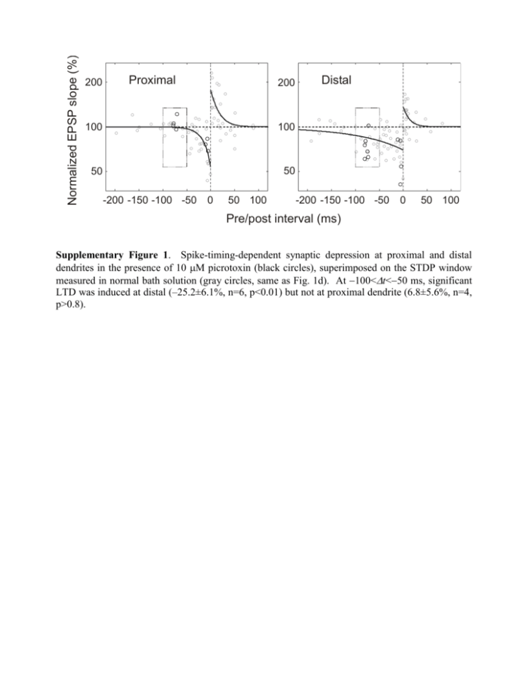
Normalized EPSP slope (%) 200 Proximal 200 100 100 50 50 -200 -150 -100 -50 0 50 100 Distal -200 -150 -100 -50 0 50 100 Pre/post interval (ms) Supplementary Figure 1. Spike-timing-dependent synaptic depression at proximal and distal dendrites in the presence of 10 M picrotoxin (black circles), superimposed on the STDP window measured in normal bath solution (gray circles, same as Fig. 1d). At 100<t<50 ms, significant LTD was induced at distal (–25.2±6.1%, n=6, p<0.01) but not at proximal dendrite (6.8±5.6%, n=4, p>0.8). a c 4AP Control 150 100 50 0 0 50 100 50 25 50 100 Spike amplitude (mV) 4 0 0 Suppr. width (ms) 75 0 8 150 50 100 150 Distance (m) e 100 0 12 150 Distance (m) d 105m Spike width (ms) Spike amplitude (mV) b Suppr. amplitude (%) 75m 35m 60 40 20 0 0 4 8 12 Spike width (ms) Supplementary Figure 2. Back-propagating APs and AP-induced suppression of EPSPs recorded from apical dendrites of L2/3 pyramidal cells. a, Examples of back-propagating APs recorded at 35, 75, and 105 m from the soma (from different cells). APs were evoked antidromically with a small stimulating electrode placed at the axon initial segment. Scale bars: 40 mV, 5 ms. b, Spike amplitude as a function of dendritic distance from the soma. Red symbols indicate experiments performed with 4-AP (3 mM) in the recording electrode. c, Spike width (measured at half-height of the AP) as a function of dendritic distance. d, Amplitude of EPSP suppression window as a function of spike amplitude. Each suppression window was fit with a single exponential 1 Ae t / ; A is used to represent amplitude. e, Width of EPSP suppression window (measured at half-height of the exponential fit, which equals log 2 ) as a function of spike width. Normalized amplitude (%) Dendritic AMPAR-EPSPs Dendritic NMDAR-EPSPs 120 120 100 100 80 80 40 dist dist prox 60 -150 -100 prox 60 -50 Pre/post interval (ms) 0 40 -150 -100 -50 0 Pre/post interval (ms) Supplementary Figure 3. Suppression of AMPAR-EPSP and NMDAR-EPSP by back-propagating AP. Same as Fig. 2e, f, except that the recordings were made in the dendrite near the stimulating electrode. n=2 to 6 (AMPAR-EPSPs) and 3 to 7 (NMDAR-EPSPs). b NMDAR-EPSP suppression (dist) 120 100 80 Control NR2A871-950 60 40 -150 -100 -50 Pre/post interval (ms) 0 Synaptic modification (%) Normalized amplitude (%) a LTD 150 100 50 0 Control NR2A871-950 Supplementary Figure 4. Expression of NR2A871-950 blocks NMDAR-EPSP suppression and LTD induction. a, Temporal windows of AP-induced suppression of NMDAR-EPSPs at distal dendrite of infected (black line, n=4) and control (gray line, n=7 to 12) L2/3 pyramidal neurons. Error bar: s.e.m. Data were significantly different over the following pre/post intervals: –10 ms (p<0.05), –20 ms (p<0.01), –30 ms (p<0.001), –50 ms (p<106), –75 ms (p<0.01), and –100 ms (p<0.05); t test. b, LTD was induced by 60 postpre spike pairs for control (–40.4±4.3%; n=18) but not for infected neurons (–5.1±3.9%; n=3; p>0.4, t test). The difference between control and infected cells was significant (p<0.001, t test). Methods. Using standard molecular biology techniques, GFP was inserted before a sequence corresponding to residues 871-950 of the NR2A subunit of the NMDAR, a serine-containing region of the C-terminus important for calcineurin-dependent NMDAR desensitization (Krupp et al., 2002, Neuropharmacology 42:593). Semliki Forest Virus (SFV) containing this construct was made by co-transfecting HEK293 cells with pSCA3-GFP-NR2A and pSCAhelper using lipofectamine 2000. After 48 hours, culture media was harvested and virus was activated with 0.5mg/ml -chymotrypsin (45 min, room temperature). Surgeries were performed in 4-week old rats in accordance with the guidelines of the Animal Care and Use Committee at the University of California, Berkeley. Rats were anesthetized with ketamine (80 mg/kg) and xylazine (10 mg/kg). Small craniotomies (1 mm 2) were performed over the visual cortex and SFV-containing media was injected into the superficial cortex with a small pipette (15 μm tip diameter). Rats were allowed to recover for two days before brain slices were cut (Takahashi et al., 2003, Science 299:1585). Infected cells were identified based on GFP labeling. Resting membrane potentials and input resistance of infected neurons were not significantly different from age-matched control neurons (p>0.3). Supplementary Figure 5. Dendritic Ca2+ signal evoked by back-propagating AP. a, Two-photon fluorescence image of a layer 2/3 pyramidal neuron filled with 200 M Oregon Green BAPTA 1. Scale bar: 20 m. b, Upper traces: Fluorescence Ca2+ signals at distal (108 m) and proximal (22 m) dendrites (white boxes in a) in response to single back-propagating APs evoked by somatic current injection, each averaged from 11 to 18 trials. Lower plot: distal vs. proximal Ca2+ signals evoked by single APs, measured by either peak amplitude () or peak area (integral, , in arbitrary units). Each symbol represents data from one cell (n=10); open symbol: with 100 M Oregon Green BAPTA 1; filled symbol: 200 M. c, 4-AP enhances the AP-induced Ca2+ signal at proximal dendrite. Upper traces: Ca2+ signals at proximal dendrite of the cell shown in (a) in the presence of extracellular 4-AP and after washout. Lower plot: AP-induced Ca2+ signals at proximal dendrite after vs. before bath application of 4-AP (n=6). Method. Oregon Green BAPTA 1 (100-200 M, Molecular Probes) was loaded into the cell via the somatic whole-cell pipette (loading time before imaging: ~15 min). Imaging was done using a twophoton laser scanning system consisting of an upright microscope (DM LFS, Leica Microsystems, Heidelberg) with 40×W0.8IR objective and a “Tsunami” titanium-sapphire laser pumped by a “Millennia” neodymium yttrium vanadate solid state laser (SpectraPhysics, Mountain View, CA), which provides <100 fs pulses at 890 nm at 80 MHz. Line-scan mode was used to record single AP-induced Ca2+ transients (temporal resolution: 1 ms). At each dendritic location, 5 to 71 sweeps were measured (interleaved between distal and proximal sites), and results were averaged. Change in Ca2+ concentration is given in the change of fluorescence normalized by baseline fluorescence (ΔF/F) after background correction. Data were analyzed in Matlab (MathWorks). a - b 30 ms 15 ms 7.5 ms 3 ms Probability Stimulus + Presynaptic spike trains 9 ms 0 18 ms c 50 67.5 ms Postsynaptic spike train Synaptic modification (%) 37.5 ms 0 -50 50 ms -100 0 100 Pre/post interval (ms) d ... ... ... ... ... ... ... ... Synaptic weight Before training 1 0 0 1 15 30 45 (ms) 60 75 0 0 1 15 30 45 (ms) 60 75 0 0 1 15 30 45 (ms) 60 75 0 0 15 30 45 60 75 30 45 60 75 (ms) Synaptic weight After training 1 0 0 1 15 30 45 (ms) 60 75 0 0 1 15 30 45 (ms) 60 75 0 0 1 15 30 45 (ms) 60 75 0 0 15 (ms) Supplementary Figure 6. Further analyses of the model on location-dependent input selection. a, Sensory stimulus used in simulation and spike trains of example model neurons. Number on the right of each presynaptic spike train indicates time constant of impulse response function of the cell (isee Supplementary Methods). To effectively illustrate the relative spike timing, spike trains are shown for a selected period with high-frequency bursts from many presynaptic neurons; the overall mean firing rate of the cells were much lower. b, Cross-correlogram between pre- and postsynaptic spike trains. Warmer colors represent inputs with more transient responses (numbers on the right indicate i). The number of pre/post spike pairs contributing to LTP and LTD can be roughly estimated from the dark and light shaded areas under each curve; dark shading: width of LTP window in c (+=12.5 ms), light shading: width of LTD window (=103.4 ms). c, Single exponential fit of the STDP window measured at distal dendrites. d, Simulation results of a 4compartment model. Shown are diagram of synaptic inputs (upper), and synaptic weight vs. i before (middle) and after (lower) training. The location dependence of input selection is similar to that found in the 2-compartment model (Fig. 5b).

