Customizing Virtual Networks with Partial FPGA Reconfiguration
advertisement
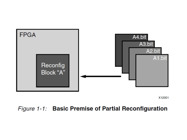
Benefits of Partial Reconfiguration • Reducing the size of the FPGA device required to implement a given function, with consequent reductions in cost and power consumption • Providing flexibility in the choices of algorithms or protocols available to an application • Enabling new techniques in design security • Improving FPGA fault tolerance • Accelerating configurable computing Definitions Partial Reconfiguration (PR) Partial Reconfiguration is modifying a subset of logic in an operating FPGA design by downloading a partial configuration file. Partition Logical section of the design, defined by the user, to be considered for design reuse. This is the section of the FPGA designated for PR. Definitions Configuration Frame The smallest addressable segments of the FPGA configuration memory space. Reconfigurable frames are built from discrete numbers of these lowest level elements Frame The smallest reconfigurable region within an FPGA device. Frame in Virtex-6 are 40 CLBs high by 1 CLB wide. Frame in Virtex-5 are 20 CLBs high by 1 CLB wide. Frame in Virtex-4, are 16 CLBs high by 1 CLB wide. Partition Pins • Logical and physical connection between static logic and reconfigurable logic. • Formerly known as “Bus Macros”. • Now they are automatically created for all Reconfigurable Partition ports, no manual reconfiguration is needed from the user. Partition Pins – Proxy Logic • Each partition pin is connected to a LUT, These LUTs are called “Proxy Logic” • Logically located in the Static Region • Required to be at a fixed known point to act as an interface between static and reconfigurable partitions Partition Pins Bus Macro Implementation PR Region Selection Internal Configuration Access Port (ICAP) • Port to read and write the FPGA configuration at run time • enables a user to write software programs for an embedded processor that modifies the circuit structure and functionality during the circuit’s operation. • Allows for automated runtime reconfiguration Hardware ICAP Core Example Self Reconfiguration System Two Ways to update LUTS • Modular Partial Reconfiguration: – Large changes – Full module is changed between two configurations • Difference Partial Reconfiguration – Small Changes – Modify a LUT function or a memory content Modular Layout Constraints of Modular Method • The size and the position of a module cannot be changed. • Input-output blocks (IOBs) are exclusively accessible by contiguous modules. • Reconfigurable modules can communicate only with neighbor modules, and it must be done through bus macros. • No global signals are allowed (e.g., global reset), with the exception of clocks that use a different bitstream and routing channels. Difference Based Partial Reconfiguration • Small changes on the FPGA configuration • Manually done using the FPGA Editor • What can be modified? – LUTs equations – BRAM contents and BRAM write modes – I/O standards and pull-ups or pull-downs on external pins – muxes that invert polarity, – Flipflop initialization and reset values, • What cannot be modified? – Routing – very dangerous: internal contentions. Problems with Difference Based Method • Lack of Automation – Changes must be done manually • In complex designs it is difficult to find the component you want to modify • Xilinx current support is mostly for modular based method. The Early-Access Partial Reconfiguration Design Flow (The Old Way - used by the paper) This design flow is no longer valid using newer Xilinx tools. The New Way – A little easier 1. Synthesize base system with reconfigurable module with input and output pins (XPS) 2. Create software files to manage PR Region (SDK) 3. Use Plan Ahead to manage PR Region and create bit-streams (Lots of steps here) 4. Merge bit-streams into download.bit to run on the FPGA Customizing Virtual Networks with Partial FPGA Reconfiguration • Use reconfiguration to create/modify a virtual network • Heuristic to assign networks to HW/SW • Allows for migration of virtual networks between HW and SW • Workstation handles SW while FPGA handles HW Motivation • Network applications have diverse performance requirements for underlying network infrastructure • Desire Flexibility, performance and isolation • Numerous hardware network substrates would work, but the hardware implementation overhead is too high • Need for straight-forward reconfigurationover-time method Limitations of Current State of the Art Current Implementation Pros Cons Software virtual networks on microprocessors High Flexibility and Isolation Low performance Network processors / dedicated hardware High Performance Hardware shuts down during reconfiguration (Low isolation) Low performance when reconfiguring (Low isolation) Migrate networks to software when reconfiguring Flexible High Performance Flexible Related Work • Supercharging Planet Lab (SPL) – Intel IXP Network Processors – Dedicated ternary content addressable memory (TCAM) for each forwarding table • FPGA implementation – 4 concurrent virtual networks with dedicated – Dedicated IP routers – Additional networks run in software – Switch to software when reconfiguring Related Work • Field Programmable Port Extender (FPX) – High speed switch – PR packet processing modules using APIs – Specialized software (PARBIT) for bit-stream management and generation – PR network processor – Reconfigurable Accelerator for packet processing functions Proposed Approach • Use reconfiguration to create/modify a virtual network • Heuristic to assign networks to HW/SW • Allows for migration of virtual networks between HW and SW • Workstation handles SW while FPGA handles HW System Design Partially Reconfigurable FPGA System Static Region PR Region Arbiter Header Verification Packet Classifier Checksum Verification Output Queues IP Lookup CPU Transceiver ARP Lookup Time to live (TTL) Lookup System Design Software Based System OpenVZ – lightweight virtualization apporach FPGA receives packets and send them to HW or SW CPU Transeiver sends the packet to the workstation OpenVZ processes the packet on a virtual network All processed packets go to the output queues on FPGA System Design Dynamic Virtual Network Allocation • Virtual network removal • Virtual network addition • Virtual network bandwidth adjustment – Reduction -> No effect on other networks – Increase -> Greedy Rebalancing Algorithm: Migrate lowest bandwidth to software or the highest bandwidth to hardware to make room for adjustment System Implementation Experimental Approach • • • • Used EARP design flow to generate bitstreams Used Bus-Macros Separate Verilog files for all modules Downloaded to the FPGA using JTAG Experiment Testbed Throughput of Routers Static Reconfigurable Method Why is there such a drop in performance in this method? Partial Reconfigurable Method Why is A unaffected by the reconfiguration like in previous method? There isn’t much of a performance gain between the highest performing PR and SR methods. Why? What causes the SR method to outperform the PR method as the number of Virtual Networks increases? Hot-Spot Mitigation • Use Partial Reconfiguration to swap hot and cool modules around the chip based on a thermal trigger. • Set a threshold temperature and when a module reaches that threshold, swap positions with a cool module using reconfiguration Hot-Spot Mitigation Module the size of ¼ a Microblaze Module the size of ½ a Microblaze Module the size of one Microblaze Pixel Video Processor • PR modules can be reconfigured to perform arbitrary one pixel functions • Tested to see how the reconfiguration time overhead effects the system Pixel Processor My Project: Data Adaptable Reconfiguration


