Applications - Department of Electrical Engineering
advertisement
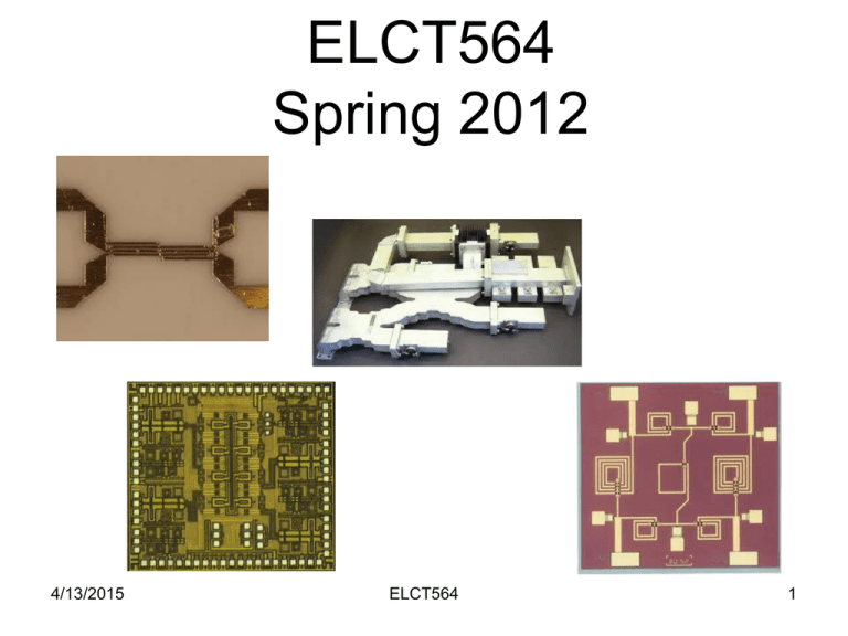
ELCT564 Spring 2012 4/13/2015 ELCT564 1 Introduction to Microwave Engineering RF and microwave engineering covers frequency from 100 MHz to 1000GHz VHF RF frequencies: 30-300 MHz RF frequencies: 300-3000 MHz UHF Microwave frequencies: 3-300 GHz mmwave frequencies: 30-300 GHz THz frequencies: >300 GHz 4/13/2015 ELCT564 2 Why study them separately? Region of EM spectrum where neither standard circuit theory (Kirchoff) nor geometrical (ray) optics can be directly applied. Because of short wavelength, lumped element approximation cannot be used. Need to treat components as distributed elements: phase of V or I changes significantly over the physical length of a device For optical engineering λ << component dimensions 4/13/2015 ELCT564 3 Approach Solve Maxwell’s equations and apply boundary conditions for the specific geometry. Hard to do for every device!!!! Analytical solutions exist only for some basic geometries and often must use numerical techniques In a lot of cases we can find V, I, P, Zo by using transmission line theory (use equivalent ckts) Not a lot of info on EM fields but sufficient for microwave and RF circuits As f increases need to use full-wave tools 4/13/2015 ELCT564 4 Why study microwaves? More bandwidth or information can be realized at higher frequencies – essential for telecommunications Microwave/mm-wave travel by line-of-sight and are not bent by the ionosphere (such as AM signals) Most of them not affected by atmospheric attenuation (space com. or secure terrestrial com.) Higher resolution radars are possible at higher frequencies Various atomic & molecular resonances occur mwave/mm-wave/THz frequencies which are important for remote sensing, radio astronomy, spectroscopy, medical diagnostics, sensing of chemical.biological agents Can get a very good salary as an RF/mmwave engineer. 4/13/2015 ELCT564 5 Applications Patriot Defense System Surface Radar 4/13/2015 ELCT564 6 Applications Global Communication Systems for the Army Air Traffic Control 4/13/2015 ELCT564 7 Applications Global Positioning System Personal Communication Systems Wireless LANs 4/13/2015 ELCT564 8 Applications Monolithic Microwave/mm-wave Integrated Circuits MRI Remote Sensing Earth and Space Observations 4/13/2015 ELCT564 9 Applications Cable and Satellite TV Aircraft and Automobile Anti-Collision Radar 4/13/2015 ELCT564 10 Application 4/13/2015 Frequency AM broadcast 535-1605 KHz Shortwave radio 3-30 MHz VHF TV (2-4) 54-72 MHz VHF TV (5-6) 76-88 MHz FM broadcast 88-108 MHz VHF TV (7-13) 174-216 MHz UHF TV (14-83) 470-810 MHz Cell phones (US) 824-849, 869-894 MHz GPS 1227, 1575 MHz PCS (US) 1850-1990 MHz Microwave Ovens 2.45 GHz Bluetooth 2.4 GHz 802.11a (wireless LAN) 5.8 GHz Direct Broadcast Satellite 12.2-12.7 GHz Services ELCT564 Collision avoidance radar 77 GHz 11 Emerging High Frequency Applications 94 GHz Personal Communications High speed microprocessor Satellite 60-G Wireless HDMI Point-to-point/Multi-point links Mobile Computing/WLAN Adaptive cruise control radar for automobiles DVD player Automotive Radar 4/13/2015 ELCT564 12 Home Networks of the Future 4/13/2015 ELCT564 13 Wireless Market Segmentation Access to PSTN Connected to Wireless Service Providers Home Office 4/13/2015 Global Enables Video Deployment Applications Access to Access to Corporate Networks Internet Service Providers ELCT564 14 Wireless Engine 4/13/2015 ELCT564 15 RF/Wireless Education: Multi-Disciplinary System Integration Basic Electromagnetics Integration Device/Circuit Design Concepts Advance CAD Techniques Current Technologies and Design Rules Modern Experimental Analysis for Circuits and Subsystems 4/13/2015 ELCT564 16 Transmission Lines “Heart” of any RF/Wireless System Coaxial Cable Parallel-Plates Twisted-Pair Rectangular Waveguide 4/13/2015 ELCT564 17 Transmission Lines Microstrip Coplanar Waveguide 4/13/2015 ELCT564 18 Substrate Materials • Semiconductors • Organic • Ceramics • Glass 4/13/2015 Silicon 11.8 GaAs 13 FR-4 4.7-4.9 Polyimide 3.5 Alumina 9.4-10 Quartz 3.5 ELCT564 19 Advanced Printed Wiring Board Technology Transmission Line Equivalent Circuit i(z,t) L Dz R Dz i(z+Dz,t) + + u(z,t) u(z+Dz,t) C Dz G Dz - Dz Microwave Bands Name Frequency L 1.12-1.7 GHz S 2.6-3.95 GHz C 5.85-8.2 GHz X 8.2-12.4 GHz Ku 12.4-18 GHz K 18-26.5 GHz Ka 26.5-40 GHz U 40-60 GHz V 50-75 GHz W 75-110 GHz EM Theory Review 4/13/2015 ELCT564 23 Maxwell’s Equations 4/13/2015 ELCT564 24 Fields in Media Loss tangent 4/13/2015 ELCT564 25 Fields at General Material Interface Dn2 Et2 Ht2 Dn1 Et1 Bn2 ..... Ht1 Bn1 Dn2 Medium 2 ..... h Medium 1 Dn1 4/13/2015 ELCT564 26 Fields at General Material Interface h 4/13/2015 Et2 Medium 2 Et1 Medium 1 ELCT564 Msn 27 Fields at a Dielectric Interface Fields at the Interface with a Perfect Conductor Fields at the Interface with a Magnetic Wall 4/13/2015 ELCT564 28 The Helmholtz Equation Source-free, linear, isotropic, homogeneous Wave Equation/The Helmholtz Equation Propagation constant/phase constant/wave number 4/13/2015 ELCT564 29 Plane Waves in a Lossless Medium Assuming electric filed only have x component and uniform in x and y directions What is the speed of light? Phase velocity Wavelength Intrinsic Impedance 4/13/2015 ELCT564 30 Plane Waves in a General Lossy Medium Complex propagation constant: Attenuation constant and phase constant 4/13/2015 ELCT564 31 Plane Waves in a General Lossy Medium 4/13/2015 ELCT564 32 Plane Waves in a Good Conductor The amplitude of the fields in the conductor decays by an amount 1/e (36.8%) after traveling a distance of one skin depth 4/13/2015 ELCT564 8.14×10⁻⁷m 6.60×10⁻⁷m 7.86×10⁻⁷m 6.40×10⁻⁷m 33 Summary of Results for Plane Wave Propagation in Various Media 4/13/2015 ELCT564 34 General Plane Wave Solutions i=x,y,z Separation of variables 4/13/2015 ELCT564 35 Circularly Polarized Waves Polarization of a plane wave refers to the orientation of the electric field vector: fixed direction or change with time. The plane waves which have their electric filed vector pointing in a fixed direction are called linearly polarized waves. Electric field polarization for (a) Right Hand Circularly Polarized (RHCP) and (b) Left Hand Circularly Polarized plane waves. 4/13/2015 ELCT564 36 Energy and Power A source of electromagnetic energy sets up fields that store electric and magnetic energy and carry power that may be transmitted or dissipated as loss. The time-average stored electric energy in a volume V The time-average stored magnetic energy in a volume V 4/13/2015 ELCT564 37 Energy and Power Poynting Vector (P0): power flow out of the closed surface S. Power Ps delivered by the sources Power dissipated in the volume due to conductivity, dielectric and magnetic losses (Pl) 4/13/2015 ELCT564 38 Plane Wave Reflection from A Media Interface 4/13/2015 ELCT564 39 Example Consider a plane wave normally incident on a half-space of copper. If f=1GHz, compute the propagation constant, intrinsic impedance, and skin depth for the conductor. Also compute the reflection and transmission coefficients (Copper’s conductivity is 5.813×10⁷S/m). 4/13/2015 ELCT564 40
