First Law for open systems (Lecture 4)
advertisement
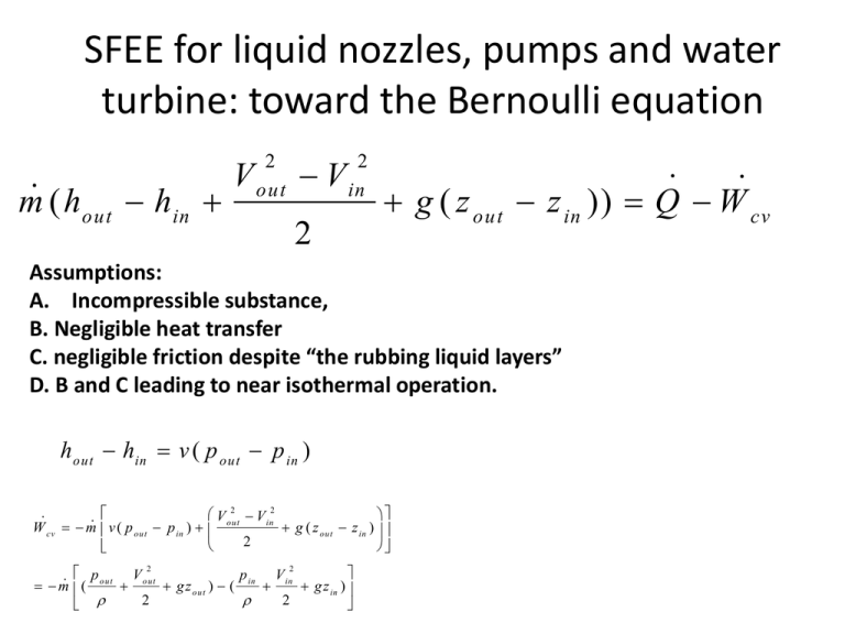
SFEE for liquid nozzles, pumps and water turbine: toward the Bernoulli equation m ( ho u t hin V 2 out V 2 in 2 g ( z out z in )) Q W c v Assumptions: A. Incompressible substance, B. Negligible heat transfer C. negligible friction despite “the rubbing liquid layers” D. B and C leading to near isothermal operation. hout hi n v ( p o ut p in ) W cv 2 2 V out V in m v ( p out p in ) g ( z out z in ) 2 2 2 p o u t V out p in V in m ( g z out ) ( g z in ) 2 2 SFEE applied to heat exchangers hot (h) cold (c) m c hc , out m h hh , out m c hc ,in m h hh ,in Take CV enclosing the stream that is hot at inlet m h ( h h , o u t h h , in ) Q Take CV enclosing the stream that is cold at inlet m c ( h c , o u t hc , in ) Q Mixing chambers or “direct contact heat exchangers” 3 2 1 m 3 m1 m 2 Conservation of mass m 1 h1 m 2 h 2 m 1 m 2 h3 Conservation of energy Throttling devices Flow restriction A device that causes a drop in pressure by restricting the flow passage can be termed a throttling device. Throttling devices Flow restriction Capillary tube expansion valve used to drop refrigerant pressure and temperature • Slow flows, DKE effects can be neglected Negligible heat transfer ( surface area ) (small devices) m ( h2 h1 V V1 2 2 2 2 )0 h2 h1 Throttling is an isenthalpic process. Fundamentally, non-quasiequilibrium. Physical effects in throttling From upstream to downstream section: • Pressure (P) drops (due to fluid-solid friction) • Velocity increases slightly • Specific volume increases • Temperature of fluid may increase or decrease or remain same (Joule Thomson effect). The fluids for which temperature decreases are candidates for use in refrigerators. – Ideal gas temperature remains same. – Incompressible substance temperature increases • Throttling of a refrigerant on T-v / P-v diagram (on board). Throttling calorimeter to measure steam quality P-v diagram? Board! Reading assignment • Cyclic processes in engineering: “Power cycles” and “Refrigeration cycles”. (Moran Section 2.6, next slide) • System integration of steady flow devices to execute composite processes and power/refrigeration cycles (Subsection titled “System Integration” of Section 4.3, next slide) Special topics (not in book, may be covered in lecture) • Differential form of the steady flow energy equation • The quasi-equilibrium steady flow heat transfer. First law analysis of a simple power cycle For the closed system shown: Q in Q o u t W t W p Do steady state open system analysis of all components. Boilers/condensers are heat exchangers where one fluid undergoes (here the working fluid of the power plant, usually steam) undergoes vaporization/ condensation Thermal efficiency of a power plant Wt W p Q in
