Avea - Webnetworks MD
advertisement
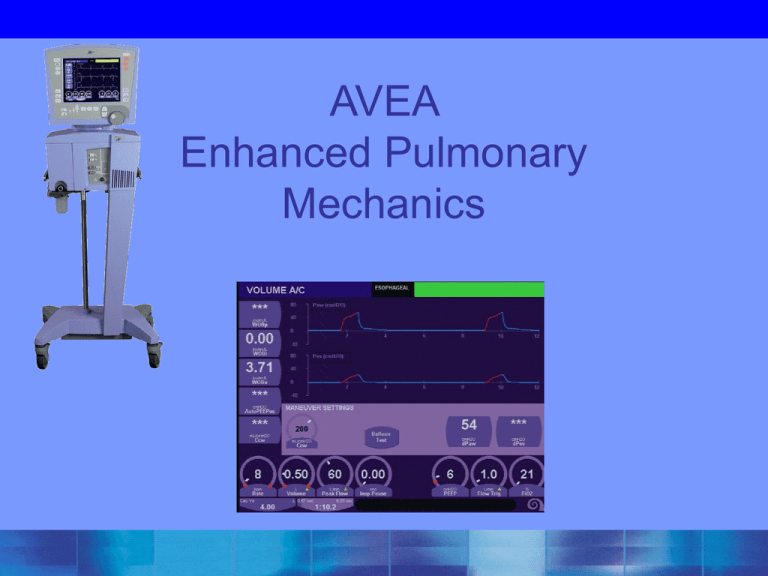
AVEA Enhanced Pulmonary Mechanics Advanced Settings User Interface Module Advanced Settings Feature Accessing Advanced Features Press “Adv Settings” hard key on left side panel of the Avea monitor to access the Advanced Settings Window Advanced Settings Window Yellow triangle indicates this parameter has Advanced Settings Activating an Advanced Setting Press the desired parameter. The parameter will then be high-lighted with a blue background. The Advanced Settings features will then appear in the window above for the parameter Advanced Settings Universal Features: Sensitivity & Pressure Support Sensitivity: Flow & Pressure Flow Trigger Advanced Settings Bias Flow Pressure Trigger Sensitivity Sensitivity • “Bias Flow” – Bias Flow enables Flow Triggering – To have adequate Flow Triggering, the Bias Flow should be set 0.5 liters above the Flow Trigger setting • Example: Bias Flow set at 2.0 litres, Flow Trigger should be set no higher than 1.5 litres • “Pressure Trigger” – The Avea has both a pressure and a flow trigger active at the same time. Whichever signal (flow or pressure) is triggered first, the ventilator will then cycle into inspiration Pressure Support Ventilation PSV Setting has 4 Advanced Settings Max Inspiratory Time Volume Limit Rise Flow Time Cycle % Pressure Support Ventilation • “Volume Limit” – Every pressure type breath on the Avea has “Volume Limit” as an Advanced Setting feature – The clinician can enter a maximum volume limit. Once the ventilator has reached this limit during the delivery of the breath, it will then cycle the breath to exhalation using volume as the cycle criteria – When the volume limit is reached, a visual display appears in the alarm area. The display remains illuminated as long as the volume limit is active • “PSV Rise Time” – Setting range is from 1 to 9, 1 being fastest and 9 slowest. – Allows the clinician to adjust the speed at which flow is delivered to the patient during a Pressure Support breath Pressure Support Ventilation • “PSV Flow Cycle %” – The Flow Cycle works as a percentage of the peak flow of the PSV breath – The Flow Cycle can be set in increments of 5% up to 45% • Example: If the flow cycle is set at 10% and the peak flow for the PSV breath is 60 lpm, the breath will cycle when the decelerating inspiratory flow curve decays to 6 lpm • “PSV Tmax” – The PSV Maximum Inspiratory Time setting allows for an adjustable back up inspiratory time setting in circumstances where flow cycling is unreliable (i.e. endotracheal tube leaks) – PSV Tmax should be set at 1.5-2 X the set Inspiratory Time for Control breaths – The PSV Tmax is adjustable from 0.2 to 5.0 seconds Advanced Settings Pressure Control Ventilation PCV PCV - Pressure Control Inspiratory Pressure Inspiratory Time Flow Trigger Inspiratory Pressure in PCV Touch Insp Pres and these settings become available Machine Volume Inspiratory Volume Limit Rise Time Advanced Settings Inspiratory Pressure in PCV • “Mach Vol” (Machine Volume) – This feature allows the clinician to set a target tidal volume during a Pressure Control breath – When Machine Volume is active, the “Mach Vol” icon appears in the modes display window Machine Volume icon Machine Volume • Is a Dual Control Mode; Ventilator delivers Volume Controlled Flow signal and Pressure Control signal to gas delivery system simultaneously. – Sets the minimum tidal volume delivered from the ventilator in a pressure control breath. – Always used with the time cycling criterion in pressure control ventilation. – Circuit compliance compensated in adult and pediatric applications. Machine Volume • Allows for the maintenance of traditional Volume Control Ventilation while allowing the ventilator to vary peak flow to meet the patient’s inspiratory flow demands • Incorporates a decelerating/ variable inspiratory flow waveform • Can be thought of as a variable flowvolume ventilation Machine Volume • Ventilator calculates the decelerating inspiratory flow required to deliver the Machine Volume (Minimum Tidal Volume) in the set inspiratory time. • When Peak Flow decelerates to this calculated peak inspiratory flow – If Machine Volume has not been delivered • transition to a continuous flow until the Machine Volume has been delivered – Inspiratory Time will remain constant » maximum Peak Inspiratory Pressure is determined by the High Peak Pressure alarm setting – If the Machine Volume is met or exceeded during delivery of the pressure control breath, the ventilator will complete the breath as a normal Pressure Control breath. Pressure Control- Volume Control Transition Pressure is increased within the breath The constant, square wave flow continues until the pre-set tidal volume is delivered Pressure Control Adjustments with Machine Volume Guarantee • Pressure Control – Decreased Compliance • Lung • Chest Wall – Neuromuscular Blockers – Increased AW Resistance • • Mucous Bonchospasm • Pressure Control – Increased Compliance • • Lung Chest Wall – Spontaneous Breathing – Decreased AW Resistance • • Post Suctioning Post Bronchodilators Machine Volume Note Inspiratory Pressure set at zero, breath is decelerating flow pressure controlled breath. (Set Mach Volume 350cc) Inspiratory time is constant Machine Volume Note transitions in flow between Pressure Control and Volume Control flow waveforms Machine Volume Vs. PRVC Machine Volume can respond to changes in compliance within 2-4 msec. PRVC will update on next breath. Compliance decreases ventilator responds within the breath Compliance increases ventilator responds within the breath Inspiratory Pressure in PCV • “Vol Limit” (Volume Limit) – This feature allows the clinician to set a maximum volume limit that cannot be exceeded during a Pressure Control breath – When the volume limit is reached, a visual display appears in the alarm area. The display remains illuminated as long as the volume limit is active • “Insp Rise” (Inspiratory Rise Time) – Setting range from 1 to 9, 1 being fastest and 9 slowest. – Allows the clinician to adjust the speed at which flow is delivered to the patient during a Pressure Control breath Volume Limit • Active in: – Pressure, – PRVC – Vsync – TCPL – PSV breaths only. – Neonatal applications Volume LimitTM requires the use of a wye flow sensor. – If a proximal flow sensor is used • Volume Limit is activated by the inspiratory tidal volume measured by the wye flow sensor. • If Volume Limit threshold has been reached: – Alarm status indicator will change to yellow and display the words Volume Limit. – Cannot be reset until the ventilator has delivered a breath, which does not meet the Volume Limit threshold. – To reset the alarm status window use the alarmreset button – Do not use with leaky ET tube Volume limit with Neonatal Flow Sensor 2 KG Inspiratory VT limit 16 ml = 8 cc/kg Volume limit can be used in conjunction with Machine volume to allow volume bracketing in Pressure Control. Machine volume is the minimum volume guarantee and Volume Limit will terminate the breath based on a maximum inspiratory tidal volume threshold. When used with only PCV, as compliance improves, so will volume. Patient will be protected from inadvertent volutrauma. Volume Limit may limit gas flow during hiccups or during increased flow demands of the patient. Inspiratory Time in PCV “Flow Cycle” is the only Advanced Setting feature for Inspiratory Time. Inspiratory Time in PCV • “Flow Cycle” – In addition to time cycling in PCV, the Avea allows the clinician the ability to add flow cycling to the inspiratory cycle criteria of the PCV breath – The Flow Cycle works as a percentage of the peak flow of the PCV breath (mimicking a Pressure Support Breath) – When a Flow Cycle percentage is set, the PCV breath can either be cycled into expiration by the percentage of Flow Cycle or Inspiratory Time depending on which criteria is met first Flow Cycle • The default setting is 0 (off) – Can be set in increments of 5% to 45% 100 Breath termination at 45% 50 Breath termination at 5% –Flow cycle can be more comfortable for spontaneously breathing patients –It can reduce mean airway pressure and VT Flow Cycle • Allows patient to determine their own Itime by terminating the breath once a certain percentage of the peak inspiratory flow is met • May improve preload and eliminate V/Q mismatching • Improves patient/ventilator dsy-synchrony • May tremendously improve oxygenation and ventilation in spontaneously breathing patients Expiratory Flow Cycling Peak Inspiratory Flow V 40% 20% 5% T Fixed Inspiratory Time No Flow Cycle Flow Cycle On Flow Cycled Breath Flow Cycle Volume Cycled Breath Flow Cycled Breath If Flow Cycle is set with Machine Volume the breath will not Flow Cycle unless the Machine Volume (Minimum Tidal Volume) has been delivered Patient Comfort • Dial in a Flow Cycle % – May apply Flow Cycle transiently to measure pt’s true I time and set IT accordingly – Flow Cycling can only occur if target tidal volume has been reached in PRVC and Machine Volume – Should only be used with patients that have low FiO2 requirements because by limiting IT Mean Airway Pressure may be affected Breath Termination Hierarchy Alarm Supercedes all other criteria Volume Limit If set, supercedes all lesser criteria Flow Cycle *In volume targeted and controlled modes only after set volume is achieved Time / Volume Cycled If no other criteria intercede Advanced Settings Volume Control Ventilation - VCV VCV - Volume Control Volume Peak Flow PSV Flow Trigger Volume Parameter in VCV Vsync Vsync On/Off Rise Time Sigh Select Volume Parameter in VCV When Vsync is selected, Volume Limit becomes apparent and the Vsync icon appears on screen. 0=Off 1=On Advanced Settings Vsync • Vsync operates similar to PRVC – Flow is only difference • Set in Vsync • Automatic in PRVC • The maximum step change between two consecutive breaths is 3 cm H2O. Volume Limit • This feature allows the clinician to set a maximum volume limit that cannot be exceeded during a Vsync breath. • When the volume limit is reached, a visual display appears in the alarm area. The display remains illuminated as long as the volume limit is active Advanced Settings Volume Parameter in VCV • “Vsync Rise Time” – Setting range from 1 to 9, 1 being fastest and 9 slowest. – With Vsync active, this control allows the clinician to adjust the speed at which flow is delivered to the patient. • “Sigh” – A sigh volume breath is delivered every 100th breath in place of the next normal volume breath. – The sigh volume breath is 1.5 times the set tidal volume Advanced Settings Peak Flow in VCV Demand Flow On/Off Waveform Type 0 = Square 1 = Ramp Intra-Breath Demand Flow • Peak Inspiratory Pressure (Ppeak) every 2 milliseconds throughout the breath cycle • “Virtual” Pressure Support Target of the greater of: – PEEP + 2 cmH2O or – Ppeak – 2 cmH2O • Maximum PEEP x 2 • Ppeak decrease by 2 cmH2O – “switch over” to Pressure Support at virtual PSV Target. • Once Tidal volume has been delivered – “looks” at the inspiratory flow • Inspiratory Flow > set peak flow – flow cycled at 25% of peak inspiratory flow • Inspiratory Flow = set flow – ends as Volume Control breath Intra-Breath Demand Flow in VCV Note augmented flow to meet patients inspiratory demand. Demand ends before set volume has been delivered. Demand continues through end of breath. Breath is FLOW CYCLED at 25% of PIFR. Intra-Breath Demand Flow ON / OFF Double cycling in periods of high demand PSV & Flow Trigger in VCV These Advanced Settings are the same for all modes and types of ventilation Advanced Settings Pressure Regulated Volume Control PRVC PRVC – Pressure Regulated Volume Control Volume Inspiratory Time Flow Trigger Volume Parameter in PRVC Similar settings to PCV since PRVC is a hybrid of PCV PRVC / Vsync • Logic controlled Volume TARGETED breath – Decelerating flow, VC test breath with a 40 msec pause – End inspiratory pressure is Target Pressure for the first pressure control breath – Subsequent breaths are delivered as pressure control breaths based on the dynamic compliance of the previous breath. • Inspiratory pressure is adjusted automatically by the ventilator to maintain the target volume. • Maximum step change between two consecutive breaths is 3 cmH2O. • Maximum tidal volume delivered in a single breath is determined by the Volume Limit setting. – Vsync NOTE: • The Peak Flow control sets the flow rate, which is used by the ventilator for the test breath only. The ventilator uses the Peak Flow setting and Inspiratory Pause to determine the maximum inspiratory time during Vsync ventilation. – Flow Cycling can only occur if target tidal volume has been reached PRVC / Vsync • This test breath sequence is initiated in the event any of the following occur: – – – – – Entering the Mode (PRVC or Vsync) Changing the set tidal volume while in PRVC or Vsync Reaching the Volume Limit setting Delivered tidal volume > 1.5 times the set volume Flow termination of the test breath • Intrabreath demand system is active for all test breaths – Exiting Standby – Activation of any of the following alarms • • • • • • High Peak Pressure Alarm Low Peak Alarm Low PEEP Alarm Patient Circuit Disconnect Alarm I-Time Limit I:E Limit – Flow Cycling can only occur if target tidal volume has been reached Advanced Settings Airway Pressure Release Ventilation APRV APRV • Patient breathes spontaneously at a CPAP level • Periodically “released” to a lower CPAP level to flush CO2 from the FRC P Question: What two features would make this type of ventilation better? APRV – Airway Pressure Release Ventilation Answer: Synchronize the changes and add PSV That’s what these Advanced Settings do. Advanced Settings Time High in APRV APRV • Allows spontaneous breathing over a high mean airway pressure. • High mean airway pressure may improve lung recruitment. • Pressure support available . • Apnea back-up parameters available. APRV Advanced settings • Time high sync period-allows the operator to allow a period in which the ventilator will synchronize (during expiration) from high to low pressure phase. – Adjustable from 0-50% of Time high. • Time high PSV-on or off-allows the user to have pressure support on or off during the time high phase. • Time low sync- allows the operator to allow a period in which the ventilator will synchronize (during inspiration) from 0-50% – Adjustable from 0-50% of Time high APRV Proposed Benefits • • • • • • • • • • 1. Lower Paw for a given tidal volume compared with volume-targeted modes, e.g., AC, SIMV 2. Lower minute ventilation, i.e., less dead space ventilation 3. Limited adverse effects on cardio-circulatory function 4. Spontaneous breathing possible throughout entire ventilatory cycle 5. Decreased sedation use 6. Near elimination of neuromuscular blockade APRV Spontaneous breaths Pressure Time High Time Low Advanced Settings Time High in APRV • “Time High Sync %” – Synchronizes transition from Pressure High to Pressure Low – Occurs with the first end of inspiration detected after the Time High Sync % window opens. – The Time High Sync %window is adjustable from 0 to 50%, in 5% increments of set Time High. – The default setting for Time High Sync % is 0 (off) Advanced Settings Time High in APRV • “Time High PSV” – Time High PSV is either turned on (position 1) or off (position 0) – The PSV is delivered above the current phase baseline pressure. – If Time High PSV is activated as Time High Advanced Setting, the ventilator will deliver the same PSV level for both Pressure High and Pressure Low. • Example: If Plow= 5cmH2O and Phigh= 25cmH2O, then a PSV breath set at 5 cmH2O will result in a Plow increase to 10cmH2O and Phigh increase to 30cmH2O Advanced Settings Time Low in APRV Advanced Settings Time Low in APRV • “Time Low Sync %” – The ventilator synchronizes the change from Pressure Low to Pressure High with the detection of inspiratory flow or the first inspiratory effort detected within the Time Low Sync % window. – The Time Low Sync % window is adjustable from 0 to 50%, in 5% increments of set Time Low. – The default setting for Time Low is 0 (off) Synchronization Window Gives a range of possible I-times if Sync is activated • Actual Time High or Time Low can change if Sync is activated • Depends on when the patient triggers to go from High to Low or Low to High PSV & Flow Trigger in APRV Both PSV & Flow Trigger Advanced Settings in VCV function as previously discussed on earlier slides Automatic Airway Compensation (AAC) • AAC when applied, will supplement spontaneous pressure support or or pressure control flow cycled breaths based on calculated endotracheal tube resistance. • Has no role in other pressure control or volume breath types. • To activate, select “AAC On” and dial in tube size and length. An indicator saying “AAC” will appear in the mode bar. How Does Tube Compensation Work? • Positive pressure added based on the inspired flow and tube curvature, diameter, and length • Patient doesn’t have to experience the resistive work due to the artificial airway AAC • Calculation based on: – ETT Size • 2.0 to 10.0 • Length – flow – pharyngeal curvature – FiO2 / gas density – transitions from turbulent to laminar flow • Only ventilator with AAC available for controlled breaths AAC (length) x (viscosity) (radius4) This equation is used during periods of laminar flow where resistance is primarily determined by gas viscosity. (density 0.75) x (viscosity .025) x (flow 1.75) x (length) (radius 4.75) This equation is used during periods of turbulent flow where resistance is primarily determined by gas density. What The Ventilator Circuit Sees Circuit Pressure • Flow triggering can be effective in minimizing imposed work Pa w What The Carina Sees Circuit pressure Lower pressure at the carina Paw What the Carina Sees Higher circuit pressure • AAC adds appropriate pressure to keep carina pressure at preset inspiratory pressure No decrease in pressure at carina Paw Considerations when using AAC • Monitor pressure support level to achieve desired volumes. Supported breaths may be augmented above pressure support, so less pressure support may be needed. • Compensatory support varies with many factors, and will vary with patient effort and other factors. • Monitor volumes and pressures carefully, with special considerations with neonates. Set-up for Patient Use (cont) Automatic Airway Compensation-suggested reading: Wrigge H, Zinerling J, Hering R,Swafenberg N, Stuber F, et al, Cardiopulmonary effects of automatic tubing compensation during airway pressure release ventilation in patients with acute lung injury Anesthesia 2001 Aug;95(2)382-9 Guttmann J, Haberthur C, Mols G.Related Articles Automatic tube compensation.Respir Care Clin N Am. 2001 Sep;7(3):475-501 AutoPEEP Airway AutoPEEP Airway AutoPEEPaw is the airway pressure at the end of exhalation immediately prior to the beginning of the next mandatory inspiration. AutoPEEP Airway Timing The ventilator will establish the AutoPEEP measurement when the system pressure reaches equilibration, at the next mandatory breath interval or 6 seconds whichever is shorter. AutoPEEP Airway Gas Trapping Normal: 0 cm H2O above the applied PEEP Note: Requires a passive patient and a cuffed endotracheal tube. Occurs when either insufficient expiratory time is present or in dynamic flow limitation conditions such as asthma or severe COPD. This results in gas trapping in the lungs. MIP / P100 Maneuver MIP Maneuver The MIP (Maximum Inspiratory Pressure) / P100 maneuver measures the negative deflection in the pressure tracing during the patient’s active effort to demand a breath. MIP Maneuver Maximum Inspiratory Pressure (MIP), is the maximum negative airway pressure that is achieved by the patient, during an expiratory hold maneuver. MIP Maneuver Normal: Adults < -70 to -100 cm H2O Pediatrics < -20 to -100 cm H2O Readiness for extubation < -20 cm H2O Note: Patient effort variable. Indicator of inspiratory muscle strength. Useful in weaning and progression of neuromuscular disease. Will be decreased in conditions such as kyphoscoliosis, advanced age, COPD and neuromuscular disease. . P100 Maneuver Respiratory Drive (P100), is the negative pressure that occurs 100 ms after an inspiratory effort has been detected. P100 Maneuver Normal: -1 to -4 cm H2O Adults -0.5 to -4 cm H2O Pediatrics Note: The pressure that occurs 100 milliseconds (ms) after the onset of inspiration while the inspiratory valve remains closed. Because it normally takes at least 300 ms for the patient to become aware of the occluded airway this is a good test of the respiratory center output. There is no change in lung volume or airflow during this initial 300 ms, therefore abnormalities in lung mechanics have no effect on the measurement. Values in excess of -5 cm H2O may indicate a high respiratory drive that may result in increased work of breathing and subsequent fatigue.
