Microprocessor and Assembly Language
advertisement
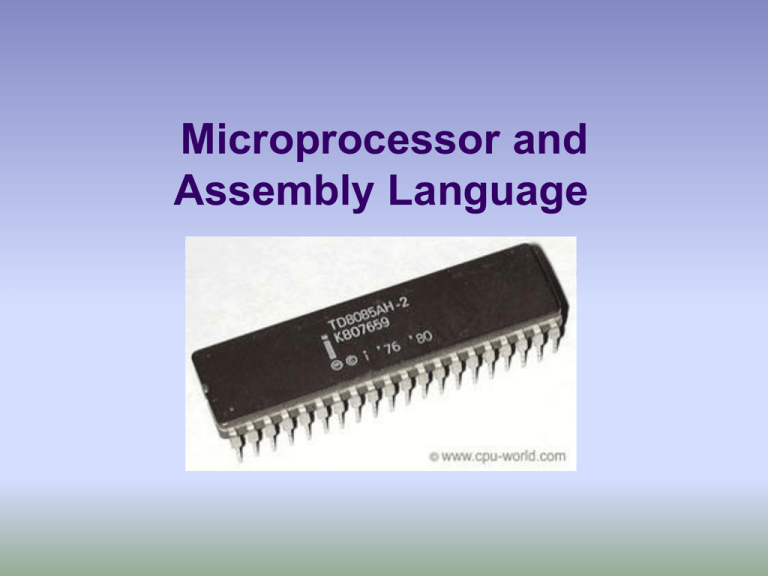
Microprocessor and Assembly Language History of Microprocessor A microprocessor (sometimes abbreviated µP) is a digital electronic component with transistors on a single semiconductor integrated circuit (IC). A Central processing unit (CPU) in a computer system or handheld device consists of one or more microprocessors. A Microprocessor is essentially a set of switches. Using photographic technology a massive set of electronic switches is superimposed onto a very small piece of silicon. Through the use of binary language, which consists of only two states; one and zero (on and off), these can be used to store information and perform operations on it. A bit refers to one binary digit; a zero or one. In computer memory and processing this refers to the state of one switch. The transistors are arranged into groups in order to represent complex numbers and instructions The very first microprocessor is considered to be the Intel 4004. It was released in 1971 and was a 4 Bit processor. Then the 8 bit 8008 microprocessor. It was developed by Intel in 1972 The first multi-chip 16 bit processor was released by National Semiconductor in 1973 Intel upgraded the 8008 into a 16 bit version they called the 8086. It was the first of the x86 family by which many modern PCs are powered. 32 bit designs didn't require much to improve performance since it has double the size of instructions as well as the amount of addressable memory. 68000 by Motorola was one of the first microprocessors developed to 32 bit architectures. It was released in 1979 and continued to be in use today. Most of today's computers are turning to 64 bit designs to handle dealing with very large amounts of data. This is needed especially as demand for 3D Graphics and fast video has risen. E.g. AMD Athlon, Pentium i5/i7 processors. Microprocessors are classified into different types on the basis of the bit of operation. Based on bit of operation at a time, the following are the types of microprocessors: ==> 4 bit. e.g. Intel 4004 ==> 8 bit. e.g. Intel 8085, 8088, Zilog Z80, Z180 ==> 16 bit. e.g. Intel 8086, 80186, 80286, 80386, ==> 32 bit. e.g. Intel Pentium, Celeron, AMD Sempron ==> 64 bit. e.g. AMD Athlon. Based on the instruction set microprocessors are classified into: RISC — Reduced Instruction Set Computing. These types of processors are commonly used in ovens, air conditioners, etc. CISC — Complex Instruction Set Computing. The types of processors are used in desktops, laptops and servers. Microcomputer Block Diagram Basic Block Diagram of Microprocessor Arithmetic and Logic Unit (ALU) Register Array Timing and Control unit ALU – Performs all arithmetic and logical operations Register array – Holds the data temporarily for processing Control Unit – It supervises/ monitors all the operations carried out in the computer The 8085 Microprocessor The 8085 microprocessor was introduced by Intel in the year 1976. This microprocessor is an update of 8080 microprocessor. The 8080 processor was updated with Enable/Disable instruction pins and Interrupt pins to form the 8085 microprocessor. It is an 8-bit microprocessor with a 40 pin dual in line package Pin Diagram of a Basic 8085 Microprocessor Intel 8085 Microprocessor Architecture 8-bit_Internal_databus Accumulator Temp. Reg Flag Reg Instruction Reg Arithmetic and Logic Unit Instruction decoder B C D E H L Stack Pointer Program Counter Incrementer/ Decrementer Address latch Address Buffer A8-A15 Data/address Buffer AD0-AD7 Timing and Control unit 8- bit External Data bus Clock Write Read RAM memory The 8085 has a set of registers for performing various operations. The various registers include: Accumulator – 8 bit register which holds the latest result from ALU B, C, D, E, H and L are general purpose registers HL pair can be used for indirect addressing as well Program counter – 16 bit register which holds the address of the next instruction to be executed Instruction register – It holds the instruction that is currently being processed. Stack pointer is used during subroutine calling and execution. Address Latch – It increments/ decrements the address before sent to the address buffer Various Flags Sign Flag:If the result of the latest arithmetic operation is having MSB (mostsignificant byte) ‘1’ (meaning it is a negative number), then the sign flag is set. Otherwise, it is reset to ‘0’ which means it is a positive number. Zero flag: If the result of the latest operation is zero, then zero flag will be set; otherwise it be reset. Auxiliary Carry Flag: This flag is not accessible to programmer. This flag will be used by the system during BCD (binary-coded decimal) operations. Parity Flag: If the result of the latest operation is having even number of ‘1’s, then this flag will be set. Otherwise this will be reset to ‘0’. This is used for error checking. Carry Flag: If the result of the latest operations exceeds 8-bits then this flag will be set. Otherwise it be reset. An example assembly language program Address Instruction 202A 202C 202E MVI MVI ADD A, 21 B, 2A B 202F STA 41 FF 2032 HLT ;Copies 21 into accumulator ;Copies 2A into B register ;Adds B reg content with Acc and stores the result in Acc. ; Stores the Acc (the sum) into the memory location 41 FF. ; Stops the program Memory storage of the Assembly language Address Instruction/Data 202A 202B 202C 202D 202E 202F 2030 2031 2032 MVI 21 MVI 2A ADD STA FF 41 HLT A, B, B Another example assembly language program Address Instruction 2020 2022 2023 2024 MVI INR MOV SUB B, 24 B A, B B 2025 STA 5F FF 2028 HLT ;Copies 24 into accumulator ;Increment B reg content by 1 ;Copies B register into Acc. ;Subtracts B reg content from Acc and stores the result in Acc. ; Stores the Acc content into the memory location 5F FF. ; Stops the program Reference: http://www.brighthub.com/engineering/electric al/articles/51225.aspx http://www.cpu-world.com/Arch/8085.html http://www.ehow.com/way_5230222_8085microprocessor-tutorial.html http://www.brighthub.com/engineering/electric al/articles/51225.aspx

