8.4.4. Electrodos
advertisement
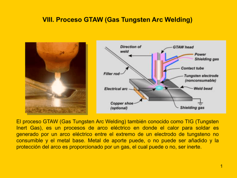
VIII. Proceso GTAW (Gas Tungsten Arc Welding) El proceso GTAW (Gas Tungsten Arc Welding) también conocido como TIG (Tungsten Inert Gas), es un procesos de arco eléctrico en donde el calor para soldar es generado por un arco eléctrico entre el extremo de un electrodo de tungsteno no consumible y el metal base. Metal de aporte puede, o no puede ser añadido y la protección del arco es proporcionado por un gas, el cual puede o no, ser inerte. 1 Plasma 2 8.1. Aplicación Actualmente el proceso TIG es ampliamente utilizado para soldar aleaciones ferrosas y no ferrosas. Aceros al carbono Aceros inoxidables Aluminio y aleaciones Aleaciones de magnesio Aceros de baja aleación Cobre y aleaciones 3 8.1. Aplicación Níquel y aleaciones (Resistente a la corrosión y a las altas Temperaturas) Zirconio y aleaciones Titanio y aleaciones (Alta resistencia a la corrosión) (Más ligero que el acero y tiene alta resistencia a la corrosión y mecánica) 4 8.2. Características del Proceso GTAW • Es muy versátil, ya que puede soldar una amplia variedad de aleaciones metálicas. • Puede ser utilizado en todas posiciones • Es bueno para soldar espesores delgados • La pileta líquida es visible al soldador • No produce escoria • El metal de aporte no es transferido a través del arco • No produce salpicaduras 5 8.2. Características del Proceso GTAW VENTAJAS • Puede ser utilizado para soldar la mayoría de las aleaciones metálicas utilizadas en la industria. • No hay escoria, por lo que no es necesaria después de soldar • No hay salpicaduras • No es necesario metal de aporte • Puede ser utilizado fácilmente en todas posiciones. • Puede ser utilizada la corriente pulsante para reducir el aporte térmico • El arco y la pileta de soldadura son visibles al soldador • Debido a que el aporte de metal no es a través del arco, la cantidad añadida no es dependiente del nivel de corriente utilizado DESVENTAJAS • La velocidad de soldadura es relativamente lento • El electrodo es fácilmente contaminado • No es recomendable para soldar grandes espesores debido a su bajas tasas de depositación • El arco requiere protección de las corrientes de aire 6 8.3. Método de aplicación • Manual • Semiautomático • Máquina • Automático 7 8.4. Equipo para el proceso GTAW 1. 2. 3. 4. 5. 6. 7. 8. Fuente de potencia Cables Antorcha Electrodo Pedal (opcional) Sistema de suministro de gas Sistema de enfriamiento Pinza tierra 8 8.4.1. Fuente de potencia Característica externa voltaje-amperes para el proceso GTAW (corriente constante) 9 8.4.1. Fuente de potencia Ciclo de trabajo • 60% - Método de aplicación manual y semiautomático • 100% - Método de aplicación a maquina y automático % CT ( I tasada ) 2 ( I c arg a ) 2 ( CT tasado ) Por ejemplo, si una máquina de soldar tiene tasada un ciclo de trabajo del 60% a 300 amp, el ciclo de trabajo de la máquina cuando es operada a 250 amp, será: % CT ( 300 ) 2 ( 250 ) 2 ( 60 ) 86 % 10 8.4.1. Fuente de potencia Ciclo de trabajo Ciclo de trabajo versus corriente de carga 11 8.4.1. Fuente de potencia Polaridad directa (electrodo negativo) Todos los metales. Para las aleaciones de Al y Mg, deben usarse procedimientos especiales Corriente directa Polaridad invertida (electrodo positivo) Poco utilizado, porque la capacidad de conducción de corriente del electrodo es extremadamente baja Direct current, straight polarity (electrode negative, DC-EN) → deep penetration Direct current, reverse polarity (electrode positive, DC-EP) → low penetration Polaridad directa e invertida 12 8.4.1. Fuente de potencia Corriente pulsante Terminología de la corriente pulsante 13 Corriente pulsante The most important weld parameters are: pulse current lp background current lG pulse current time tp background current time tG pulse frequency fp = 1 / tc Where: tc = duration of period 14 Corriente pulsante Concerning the equipment of TIG-pulsed arc welding, a relatively new pulsed arc welding process has emerged, which only modifies by the current (pulse amplitude, impulse frequency, mark-space ratio). During the impulses where high current is present in the pulse arc process, a large amount of heat is generated in the welding area. This results in fusion of the work material. In the impulse pause where low current is preset, only a little heat is transmitted into the workpiece, thus the weld pool stays comparatively cool. The low currents during the background current time only serve to maintain the arc in order to avoid interruptions and ignition difficulties. When welding with a filler, the filler will be fused with the base material during the impulse phase. The impulse frequency is usually between 0.5 Hz and 10 Hz. 15 Corriente pulsante The weld heat input can be considerably changed by the choice of times and current values. In the extreme case a weld seam can consist of fusion welding points which lie next to each other or overlap. Thanks to the TIG-pulsed arc welding, the area of application of the TIG-process can be extended to low power values thus material thicknesses can be reduced and the weld seam appearance can again be improved. For welding aluminium with a DC supply it is only possible to use helium as shielding gas. 16 Corriente pulsante Advantages: • possibility of lower energy inputs • better depth-to-width ratio in the case of higher thickness • more stable arc • more uniform root formation • better ‘out of position’ weldability • less workpiece distortion • better modulation of the welding pool • better gap bridging ability Disadvantages: • welding equipment is expensive • equipment set up is more complicated 17 8.4.1. Fuente de potencia Soldadura producida por la corriente pulsante 18 8.4.1. Fuente de potencia Corriente alterna Aleaciones de Al y Mg • Mejor acción limpiadora de los óxidos en la superficie • Mejor acción y suave acción de la soldadura • No hay reducción en la salida ajustada de un transformador convencional • Deben utilizarse de electrodos de mayor diámetro • Los sistemas del balanceo de onda lo hacen muy caro Alternating current (AC) → medium penetration 19 Corriente alterna Destruction of the Oxide Layer In the case with the electrode as cathode, the emitted electrons meet the anodic poled workpiece and, by the conversion of kinetic energy, they generate a large amount of heat on the point of contact and thus give a deep penetration. In comparison, the electrode tip is only heating up a small amount, due to the upcoming gas ions, which in contrast to the electrons show a larger mass, but generate less heat and are considerably slower than the electrons. Operating using this polarity the oxide layer is not destroyed, which in reality means that this polarity is not suitable for aluminium welding. In the case with the electrode as anode, the emitted electrons meet the electrode and heat it up rapidly. In comparison, the workpiece which is poled as a cathode is only heated a 20 relatively small amount, thus only a flat penetration arises. Corriente alterna Destruction of the Oxide Layer At this polarity a cleaning effect comes up, i.e. the oxide skin is torn apart and detached. This effect is explained by the fact that the relatively heavy ions meet the oxide skin and destroy it. At this polarity however, the high thermal load on the tungsten electrode leads to a rapid destruction of the tungsten. By using this kind of polarity several welding procedures can carried out by using disproportionately thick tungsten electrodes for thin plates. However, this kind of 21 polarisation is not generally used for TIG welding. Corriente alterna TIG welding with an alternating current is mostly used for practical fabrication. During the positive half wave a cleaning effect occurs and the tungsten electrode rapidly heats up; during the negative half wave the electrode is allowed to cool down. Consequently, the advantages of both kinds of direct current polarity are united. Since the arc goes out at every current zero crossing, it was traditionally supplied by a high frequency overlay (150 kHz at 1500 to 2000 Amps) in order to facilitate a re-ignition of the arc. These machines have now been replaced by pulse generators that do not constantly send out high frequency stress impulses, but instead supply a smooth sinusoidal voltage. This has the advantage that they are far less like to influence radio and TV receptions in the close environment and, as a consequence, do not have to be signed up at the federal post office. 22 8.4.1. Fuente de potencia Fuentes programables que permiten el método de aplicación automático 23 8.4.1. Fuente de potencia Tipo de fuentes de potencia según sus características constructivas Estáticas Tipo transformador-rectificador 24 8.4.1. Fuente de potencia Tipo de fuentes de potencia según sus características constructivas • Rotativas Tipo motor generador de combustión interna Tipo motor generador 25 8.4.2. Cables 26 8.4.3. Antorcha 27 8.4.3. Antorcha 28 8.4.4. Electrodos • Tungsteno puro (W) • Zirconio -Tungsteno (Zr-W) • Thorio – Tungsteno (Th-W) •Lantano -Tungsteno (La-W) • Cerio – Tungsteno (Ce-W) • Itrio -Tungsteno (I-W) 29 8.4.4. Electrodos Clasificación AWS % W (mínimo) por diferencia Th % Zr % Total de otros elementos EWP 99.5 - - 0.5 EWTh-1 98.5 0.8 – 1.2 - 0.5 EWTh-2 97.5 1.7 – 2.2 - 0.5 EWTh-3 (a) 98.95 0.35 -0.55 - 0.5 EWZr 99.2 - 0.15-0.40 0.5 Clasificación de los electrodos de Tungsteno (AWS A5.12) Composition EN-Classification Tungsten (pure) WP Tungsten with 1% thoria WT 10 Tungsten with 2% thoria WT 20 Tungsten with 3% thoria WT 30 Tungsten with 4% thoria WT 40 Tungsten with 0.8% zirconia WZ 8 Tungsten with 1% lanthana WL 10 Clasificación de los electrodos de Tungsteno (EN-Norma europea) 30 8.4.4. Electrodos 31 8.4.4. Electrodos W The pure tungsten electrode is the one without any addition of oxide. It has a low current capacity and is easily burnt. It is suitable for application under the condition of AC and in the situation of low welding requirement 32 8.4.4. Electrodos Zr-W Zirconiated Tungsten Electrodes have good performance in AC welding. Especially under high load current its excellent performance can not be replaced by any other products. 33 8.4.4. Electrodos Th-W Thoriated tungsten electrode is a good general use tungsten for DC applications, because it operates well even when overlload with extra amperage, thus improves the performance of welding. 34 8.4.4. Electrodos La-W The lanthanated tungsten electrode has outstanding welding performance without radiation hazard. And its electric conductivity is the most close to that of 2% thoriated tungsten electrode. It enable welders to replace the thoriated tungsten electrode by lanthanated tungsten electrode easily and conveniently without any change in welding procedure. Therefore, lanthanated tungsten electrode is the most popular replacement of 2% thoriated tungsten in Europe and Japan. Lanthanated tungsten electrode is normally applied in DC (Direct Current) welding, it also works well in AC (Alternate Current) welding. 35 8.4.4. Electrodos Ce-W Cerium tungsten electrodes have easy arc starting performance and low are keeping current. It is especially used to weld pipes, stainless steel articles and fine miniparts 36 8.4.4. Electrodos Características de la punta del electrodo 37 8.4.4. Electrodos Características de la punta del electrodo Electrode taper is usually called out in degrees of included angle, usually anywhere between 14 and 60 degrees. Grinding an electrode to a point aids arc starting when depositing short-duration welds on small parts. However, in most cases a flat spot or tip diameter at the end of electrode works best. 38 8.4.4. Electrodos Afilado de la punta 39 8.4.5. Pedal 40 8.4.6. Suministro de gas 41 8.4.7. Sistema de enfriamiento 42 8.4.8. Pinza tierra 43 8.5. Gases protectores 44 8.5. Gases protectores In the case of aluminium, the argon offers a calm and stable metal transfer. However it has a lower penetration intensity and its security against porosity (due to hydrogen) is not as resistant as argon-helium mixtures. Helium is not an appropriate shielding gas because of its very uneven coarse drops and often with background current burdened metal transfer. Effective combinations of helium and argon have been found to lie between 3070% of each respective gas. Most commonly used is a mixture of 50% argon and 50% helium. The pre-heat expenditure can be reduced or totally avoided by using heliumbearing mixtures. For increasing the weld penetration it is possible to add in O2 or CO2 between 150 and 300 vpm instead of N2. 45 8.5. Gases protectores Argon Concerning TIG-welding with negative polarisation of the electrode, a method has been developed which, instead of the usual inert-gas argon, makes use of the helium gas. This is based on special characteristics of this gas. Due to the higher ionisation energy of helium compared to argon, a greater welding voltage (approximately 75% greater) provides the same amount of amperage and this leads to a higher thermal input into the workpiece. The higher heat conductivity of helium is another advantage compared to the argon. Because of its lower conductivity of electricity, a disadvantage of helium is the production of a turbulent arc and difficult arc ignition when TIG-welding. 46 8.5. Gases protectores Argon In a lot of cases, mixtures of argon and helium result in a usable compromise. From an economical point of view it also has to be considered that helium is more expensive than argon. In addition, due to its lower specific weight, comparatively more helium than argon has to be used for gas shielding purposes. The higher energy input by helium results in an increased welding speed, lower pre-heat temperatures at the same penetration, and a lower tendency for porosity by a hotter weld pool with lower viscosity and better degasification possibilities. TIG-welding of aluminium workpieces with an increasing usage of helium will be introduced in future, particularly at machinery welding. 47 Helium The shape of the arc is also mainly influenced by the type of inert gas used. This is predominately due to the physical characteristics of the gas and respective thermal conductivities, also the dissociation of the active gases have an influence. The figure shows the influence of the inert gas on the penetration profile on plate TIG welds in aluminium using different shielding gases. +300 vpm NO +70 vpm N2 Argon Helium Argon 4.6 48 49 8.6. Metal de aporte 50 8.6. Metal de aporte Especificación para aleaciones de Al (AWS A5.10) 51 8.6. Metal de aporte Especificación para aleaciones de Mg (AWS A5.19) 52 8.6. Metal de aporte Especificación para aceros inoxidables (AWS A5.9) 53 Soldadura por fusión Arco eléctrico Oxigas (llama) 54 Soldadura oxiacetilénica Three basic types of oxyacetylene flames used in oxyfuel-gas welding and cutting operations: (a) neutral flame; (b) oxidizing flame; (c) carburizing, or reducing, flame. The gas mixture in (a) is basically equal volumes of oxygen and acetylene. 55 (a) General view of and (b) cross-section of a torch used in oxyacetylene welding. The acetylene valve is opened first; the gas is lit with a spark lighter or a pilot light; then the oxygen valve is opened and the flame adjusted. (c) Basic equipment used in oxyfuel-gas welding. To ensure correct connections, all threads on acetylene fittings are left-handed, whereas those for oxygen are right-handed. Oxygen regulators are usually painted green, acetylene regulators red. 56 Proceso FCAW (Flux Cored Arc Welding) 57 Proceso GMAW (Gas Metal Arc Welding) 58 Proceso SAW (Submerged Arc Welding) 59 Proceso SMAW (Shielded Metal Arc Welding) 60 Proceso GTAW (Gas Tungsten Arc Welding) 61 Plasma 62 Electroslag 63 Principales procesos de soldadura por fusión 64 Particularidades de la soldadura por fusión •Ocurre a alta temperatura de calentamiento •Transcurre con gran velocidad. •Se caracteriza porque los volúmenes calentado y fundido son muy pequeños. del metal •Durante la soldadura tiene lugar una rápida transferencia de calor del metal fundido, del baño de fusión a las zonas del metal de base en estado sólido, adyacentes a él. •Sobre el metal depositado en la zona de soldadura actúan intensamente los gases y escorias que le rodean. •El metal de aportación, cuya composición química puede diferenciarse considerablemente de la composición química del metal base se emplea en una serie de casos para formar el metal del cordón. 65 ZONA FUNDIDA 1. 2. 3. 4. Modificaciones químicas Absorción de gas Precipitación de compuestos Transformaciones estructurales 66 1. Modificaciones químicas Las variaciones en la composición química de la zona fundida pueden tener una influencia favorable o desfavorable sobre las propiedades de la unión soldada. Pérdidas por oxidación - Si, Mn y C. Fijación de elementos -Elementos sólidos: C, P y S -Elementos gaseosos: N, O e H 67

