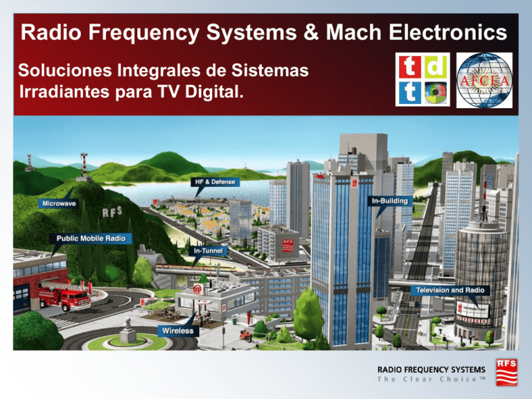
Radio Frequency Systems & Mach Electronics
Soluciones Integrales de Sistemas
Irradiantes para TV Digital.
TV & Radio
Soluciones Integrales de Sistemas
Irradiantes para TV Digital.
RFS – Es la única compañía mundial que fabrica el paquete completo
de un Sistema Irradiante.
3
© Radio Frequency Systems 2011 All rights reserved
Broadcast combiners
RFS specialises in combining
solutions that allow broadcasters
to maximize value from their
broadband antenna systems
investment.
Combining solutions:
• Available for FM radio, DAB, digital and
analogue television and MMDS
requirements
DTV adjacent channel combining
• RFS is a pioneer in the development of
adjacent channel combining for the
addition of digital television services
Compact UHF waveguide combiner
• The RFS UHF waveguide combiner has
the most compact footprint of any
waveguide combiner on the market
4
© Radio Frequency Systems 2011 All rights reserved
Broad power range
•High and low power solutions are available
from less than 10 watts to 200 kW
Broadcast combiners
5
© Radio Frequency Systems 2011 All rights reserved
Broadcast patch panels
Patch panels allow the RF switching
of FM radio and television services
in all bands.
Customised design
• Patch panels are made to order, but a
range of standard panels are available
Rapid release U-Link
• RFS uses the rapid release U Link for
ease of operation and reliability
Patch panel options
• A range of power splitters as well as
power and VSWR monitoring
solutions and touch screen displays
are available and can be incorporated
into the patch panel design
6
© Radio Frequency Systems 2011 All rights reserved
Broadcast patch panels
7
© Radio Frequency Systems 2011 All rights reserved
HELIFLEX® and CELLFLEX®
Líneas de transmisión RFS
dieléctrico aire y foam
RFS tiene fabrica cable aire HELIFLEX®
para la industria de broadcast y HF
por más de 50 años.
• Tamaños desde 3/8 de pulgada hasta 9
pulgadas
• RFS es el único proveedor que fabrica
cables semi-flexibles
de 6-1/8” y arriba
8
© Radio Frequency Systems 2011 All rights reserved
Broadcast antennas
Comprehensive range
• RFS manufactures a full range of
antennas for television, FM radio and
DAB applications including digital
applications. Panel, slot and side-mount
antennas available for most frequency
bands.
Customised antenna solution
• Patterns tailored to meet any coverage
requirement
To suit a range of towers and mounting
arrangements
To meet special requirements for a
variety of environmental conditions
Fully featured
• RFS antennas are wide-band and are
designed to support multiple channels
9
© Radio Frequency Systems 2011 All rights reserved
Available in pressurised and
unpressurised formats.
A range of radome options.
Soluciones Integrales de Sistemas
Irradiantes para TV Digital. - Ejemplos
10
© Radio Frequency Systems 2011 All rights reserved
Torres en morro Sumaré - SP
11
© Radio Frequency Systems 2011 All rights reserved
SBT
Antena UHF para servicio Digital
Modelo PHP30E
Doble alimentación
Torre SBT
+ 2 líneas coaxiales 5”
+ Switch Frame (Patch Panel
6 puertas)
+ Líneas Rígidas
+ Deshidratador
+ Servicio de instalación
12
© Radio Frequency Systems 2011 All rights reserved
SBT
13
© Radio Frequency Systems 2011 All rights reserved
REDE TV
Antena UHF para Servicio
Digital Modelo PHP120O
Doble alimentación
Torre
REDE TV
+ 2 líneas coaxiales
+ Switch Frame (Patch Panel
6 puertas)
+ Líneas Rígidas
+ Deshidratador
+ Servicio de instalación
14
© Radio Frequency Systems 2011 All rights reserved
REDE TV
15
© Radio Frequency Systems 2011 All rights reserved
BAND – Ave Paulista x Rebouças
16
© Radio Frequency Systems 2011 All rights reserved
BAND
Antena UHF para
Servicio Digital
Modelo PHP30 O
Antena UHF para 3
servicios Digitáis
Modelo PHP120 O
+ 2 Líneas coaxiales 6”
+2 Líneas coaxiales 4”
+Combinador en Guía de
Onda
+ Switch Frame (Patch Panel
6 puertas)
+ Líneas Rígidas
+ Deshidratador
17
© Radio Frequency Systems 2011 All rights reserved
TV GLOBO – Calle Alameda Santos
18
© Radio Frequency Systems 2011 All rights reserved
TV GLOBO
Antena VHF para servicio
análogo Canal 5
Modelo 661 CP
Antena UHF para
servicio Digital
Modelo PHP40 E
19
© Radio Frequency Systems 2011 All rights reserved
Argentina
Antenas de Polarización Vertical
UD Series
Broadband design for Digital TV or multi-channel use
• Designed for maximum corrosion protection
• Vertically polarized
• Pressurized
• Low wind loading
20
© Radio Frequency Systems 2011 All rights reserved
Argentina
PHP Panel Array Antennas
PHP 18
• Corrosion resistant aluminium construction with
fibreglass radome
• Horizontal polarization
• Low wind loading
• Full band operation
• High power rating
21
© Radio Frequency Systems 2011 All rights reserved
Argentina
Integración en Planta local
22
© Radio Frequency Systems 2011 All rights reserved
Argentina
Puesta en marcha de las antenas
23
© Radio Frequency Systems 2011 All rights reserved
Argentina
Traslado y izado de líneas de transmisión
24
© Radio Frequency Systems 2011 All rights reserved
Argentina
Armado de
conectores
Prueba de
aceptación
Presurizado de
las líneas de
transmisión
Conexión al
grupo
Transmisor
25
© Radio Frequency Systems 2011 All rights reserved
Nuevas Tecnologías
26
© Radio Frequency Systems 2011 All rights reserved
Introduction
ISDB-T, TDT DVB, DVB-T, ATSC-M/H Standards Are in Place in
LATAM
ALL of These Standards Support Broadcast to Mobile Receivers
This is THE Time for Broadcasters to Move Ahead of Competitive
Delivery Methods (Satellite, Cable) While Keeping The System
Flexible Enough for Future Enhancements/Expansion
What Does the Broadcaster Need to do to Take Advantage of
Standards and Technology to Gain An Advantage Over Competitive
Delivery Methods and Competitor Stations?
27
Polarization Diversity……
© Radio Frequency Systems 2011 All rights reserved
Polarization Diversity Continued
Studies Have Shown That by Adding a Vertical Component to the
Radiated Signal Increases the Margin at the Receiver by 2 to 11db
How Can This Be Achieved?
Elliptical Polarization or Circular Polarization From a Common
Array
Is There a Way to Upgrade The Antenna System Today While
Allowing for Future Polarization Ratio Changes As the Business
Model Focus Transitions to Mobile?
Absolutely-Using Variable Polarization Technology (VPT)!
29
© Radio Frequency Systems 2011 All rights reserved
Variable Polarization Technology (VPT)
VPT Allows for Each Channel in a Master Array to be Operating with a
Polarization Ratio Independent of the Ratios of Other Channels
Operating in the Same Array
Stations can Operate Horizontal Polarization, Elliptical Polarization and/or Circular
Polarization Simultaneously in the Same Array
Why is This Important?
Today’s Polarization Ratio is Typically 100% Horizontal (Just Upgraded DTV
Transmitter) and Additional Transmitter Upgrades in Coming Years
Determining What the Right Polarization Ratio Can be Dependant on Channel of
Operation, ERP, Terrain, Competition, Transmitter Limitations…Not the Same For
Every Broadcaster
The Polarization Ratio May Change as the Business Model Matures and Supports
Mobile Reception
System is Future-Proof! Allows for Future Polarization Ratio Changes Without
Antenna System Changes!
Allow Stations to Leap Frog the Competition on Their Time Frame
30
© Radio Frequency Systems 2011 All rights reserved
Master Antenna Systems
Polarization Ratio – PEP* - User Variable Polarization *Patent Pending
User Variable
Polarization
Pair of Phase
PEP
ARRAY
Matched Combiners
and Feeders
Adjust Phase at
Power Splitter to Set V
and H Ratio for Each
Broadcaster
Simple Adjustment
+45° A N TE N N A
IN P U T
-45° A N TE N N A
IN P U T
-45° C O M B IN E R
A D JU S T
PHASE
-45° FE E D E R
at Ground Level
TX 1
TX 2
Sample Points at
Various Locations for
Verifying Correct Setup
31
© Radio Frequency Systems 2011 All rights reserved
TX 3
TX 4
EQUAL POW ER
S P LITTE R S
+45° FE E D E R
+45° C O M B IN E R
Master Antenna Systems
UVP Adjustable Power Splitters
12 Variable Power Splitters
Integrated Into Patch Panel System:
33
© Radio Frequency Systems 2011 All rights reserved
PEP Antennas
Low Wind-load
Radome Profile
34
© Radio Frequency Systems 2011 All rights reserved
Band IV/V (UHF) PeakPower+TM bandpass filter.
•
35
The Peak Power+ line of filters and
combiners have been specifically
conceived for the very high peak-toaverage power ratio nature of digital
television (DTV), and represent
a breakthrough in coaxial filter
technology.
© Radio Frequency Systems 2011 All rights reserved
Band IV/V (UHF) PeakPower+TM bandpass filter.
• Very compact for easy integration into
equipment.
• Very low insertion loss for filter size,
(lowest IL for this size).
• Highest power rating for size/class of filter.
• Tunable over full UHF band (470 – 862
MHz)
• Adjustable bandwidth, available for 6, 7 & 8
MHz channels for global
applications.
• External, non-invasive coupling
adjustment.
• Tunable for both ETSI and ISDB-T critical
and non-critical, and ATSC
applications.
• -5 to 55 degree ambient temperature
operation.
36
© Radio Frequency Systems 2011 All rights reserved
Argentina
Video
37
© Radio Frequency Systems 2011 All rights reserved
Muchas Gracias
Ricardo Avena
Phone: +55 11 4785-6033
Mobile: +55 11 9180-9303
e-mail: ricardo.avena@rfsworld.com
38
© Radio Frequency Systems 2011 All rights reserved

