Presentation
advertisement

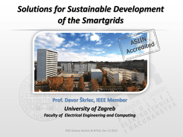
Solutions for Sustainable Development of the Smartgrids Prof. Davor Škrlec, IEEE Member University of Zagreb Faculty of Electrical Engineering and Computing IEEE Greece Section & NTUA, Dec 13 2012 FER Map Skyscraper Main entrance 43308 m2 FER in numbers Undergraduate students ~ 4300 Postgraduate students ~ 450 Freshmen each year ~ 650 Graduating students each year ~ 550 Graduated since 1956 (Dipl.Ing.) ~ 16000 Graduated since 1956 (M.Sc.) ~ 2100 Graduated since 1956 (Ph.D.) ~ 630 Bachelors Degree • Duration: 3 years, 180 ECTS • Bachelor level (3 years) Electrical engineering and information technology Computing Masters degree • Duration: 2 years, 120 ECTS • Electrical engineering and information technology • • • • • Control engineering Electrical power engineering Electronic and computer engineering Electronics Electrical engineering systems and technology • Information and communication technology • Information processing • Telecommunications and informatics • Wireless technologies More info … • Progress Report and more information available on: http://www.fer.unizg.hr/en Sustainable development of the Smartgrids My interest is in the future because I am going to spend the rest of my life there. Charles F. Kettering (1876 - 1958) (engineer, scientist, inventor) What we need ? EU technology platform - general policy (SGGA;SET Plan) industry initiative (EEI;EEGI;EURELETRIC) network operators (EEGI;ENTSO-E;EDSO4SG) demonstration projects (FP7;Smartgrids ERANet) technical solutions costs/benefits business models standards and regulation (ACER;CENELEC;IEC) customers market Solution No. 1 Distribution Network Optimization-CADDiN CIRED 2011 poster session – paper 1252 – session 5 CADDiN Computer Aided Design of Distribution Network Data preparation in CADDiN Map Module AutoCAD MAP Add-on Connection cost assignment o o o o Optimization Existing cable Ex-line route Corridor Custom cost Evolutionary algorithm Adjusted VRP algorithm Various output topologies Results Visualization and simple analysis in CADDiN Map Module Feeder Support point Consumption station Cable Backup cable Distribution Network Optimization-CADDiN (results in Google Earth) OGULIN SUPPLY AREA Consumption concentrated in urban area Two big radial areas – low consumption Approximated with single consumption point Connection cost Existing cable (Blue on picture) Ex-line route Existing overhead lines (Red on picture) Corridors determined by Urban Planning (Orange on picture) Corridors All roads User defined (by experience) Solution layout – Closed loop (ring) Solution No. 2 Input data - BAU 13 Input data - BAU (2) Result of data integration - BAU • several months later... Summary of BAU • building the network for calculation – long term job (months) – data quality/accuracy • distributed and non-uniform data update • local organizational units have more accurate data – all resources-consuming job of checking network topology and data after initial network building • waste of time (money) – after some time network model is uncompatible with real network Network data in GIS network data in GIS – updated and accurate – spatial character – network model for calculations in minutes not in months DeGIS (customize application in SmallWorld) Network data in DeGIS Transfer of data to NEPLAN • Transfer from DeGIS – all objects “after and on the same voltage level” of selected object – all object “after” selected object • possibility to stop tracing on switching elements depending on switch status • transfer of simplified geometry – start/end point of line – full data model is not necessary for calculation purposes Network data in NEPLAN Network data in NEPLAN (2) Network data in DeGIS Network data in DeGIS (2) Representation in NEPLAN Network data in DeGIS(3) Representation in NEPLAN Representation in NEPLAN NEPLAN to DeGIS • network data and calculations results - simple return to DeGIS – IT WORKS ! Further improvements • calculations within DeGIS + NEPLAN as external application + unnecessary export/import of data + instantenously visible calculations results + user-friendly application + and more ... Solution No. 3 Power Quality Monitoring in Distribution Network 21 distribution regions 100 supply points 110 kV 300 TS 35/10 kV 20 000 TS 10/0,4 kV 2 300 000 customers most of 110 kV supply points are equipped with power quality analyzing units, but only some of them are connected to the related control centre since every region develops according its own policy, there was no unified approach what kind of measuring, control or protection equipment is used in distribution TS most of TS are equipped with PLCs, DMM, numeric relays or bay controllers with communication ability, but none of them is yet used for PQ data acquisition Optimization of Existing Resources SCHEDULED TASKS: detailed analysis of the entire monitoring equipment installed in distribution networks in Croatia defining monitoring and measurement capabilities of the installed equipment determining communication links to distribution centers defining common warehouse for PQ monitoring data defining final solution PQ Data Sources SCADA systems data are collected in control centre from remote station computers using WAN PQ data are preprocessed and exported in appropriate file format IED - Intelligent Electronic Devices numeric relays bay controllers, DMM - digital multimeters power analyzers data are collected in local PQ-IPC using local process bus (MODBUS) PQ data are preprocessed and exported in appropriate file format PQ Data Sources cont. AMR systems data are collected in control center using PSTN, GSM/GPRS or Ethernet network PQ data are preprocessed and exported in appropriate file format meters of new generation can acquire PQ relevant data, but this feature is useful only if high-speed communication is available (WAN) PQ MONITORS «. » new generation of IED specially provided for PQ data acquisition ^ local data processing processed data can be directly transferred to the related control centre PQ Data Acqusition Concept (TS 35/20/10 kV) Control centre PLC, PAC numeric relay, bay controller AMR DMM, network analyzer PQ-MONITOR numeric revenue meter Low voltage network/Households TS 10/0,4 kV PQ monitoring device simple and inexpensive device capable to measure all the required PQ parameters PQube - power monitor Power Quality monitoring: Voltage dips, swells, and interruptions Waveforms and RMS graphs Over-frequency and under-frequency events 1microsecond high-frequency impulse detection THD, TDD, and time-triggered snapshots Voltage and current unbalance. RMS Flicker - Pinst, PST, PLT Detailed event recording, plus daily, weekly, monthly trend Energy monitoring: Watts, VA, VAR's, true Power Factor, Watt-hours, VA-hour Peaks: single-cycle peak, 1-minute, and 15-minute averac Daily, weekly, monthly trends. Load duration curves No software required: Spreadsheets: CSV files; events, trends, statistics. Pictures: Event and trend/statistics graphs in GIF format PQDIF: the IEEE's standard for power quality data files. Text, XML, and HTML summaries Easy data retrieval: Ethernet: Built-in web server - retrieve meters, files, graphs FTP server for easy file transfer Modbus-TCP Thank you for your attention Contact: Email: davor.skrlec@fer.hr HTTP: www.fer.unizg.hr/davor.skrlec Skype: davor318456


