Electrification
advertisement
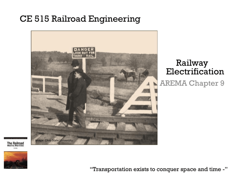
CE 515 Railroad Engineering Railway Electrification AREMA Chapter 9 Image: Ohio State University “Transportation exists to conquer space and time -” Electric Traction Development • 1835: Thomas Davenport – developed electric railway using a model railroad with a third rail • 1879: Werner von Siemens – first practical electric railway • 1890: Siemens' brothers - London underground railway (two 50 hp motors) • 1898: Arthur Koppel introduced mass production battery and electric locomotive in the US Image: Getty (under fair use) Image: Mike’s Rail History prior to 1935 Image: Mike’s Rail History prior to 1935 Image: Scientific America Supplement 2 Electric Traction Development • 1895: first electric train in the US • Power was supplied at 550 to 675 VDC • 1905: Railways started using and converting DC to AC power with up to 25 kV • Example of power used in the US: Image: 1902, viewliner LTD Image: Eric, 2009 – High speed: 12.5 – 25 kV – Heavy haul: 25 – 50 kV – Commuter: 650 – 12 kV • Most efficient found in 1960s was 25 kV 3 Image: City of Montreal Electric over Diesel-Electric • Straight-Electric Advantages: – Higher speeds and low-end torque – Able to utilize multiple power sources (coal, nuclear, hydroelectric) – Minimize local air emissions – Can employ regenerative braking to add electricity to the grid – Can improve capacity without adding infrastructure • Diesel-Electric Advantages: – Lower initial capital cost – Does not require elaborate electrical grid system – Can operate during any power state and in areas where power cannot be reached easily – Minimizes electrical safety hazards to the public with no exposed high-voltage rails or wires. 4 • Street Car • Advance Light Rapid Transit Image: RTD Image: City of Toronto • Light Rail Image: MARC Image: Metro • Heavy Haul • Commuter Rail • Metrorail Image: Eric http://www.flickr.com/photos/90001203@N00/3125900050 • Inter-City 5 Image: University of West Virginia Existing Electrification Systems Elements of an Electrification System • Sources of primary power • Substations to transform the power into a form suitable for train operations • Power distribution system • Current collectors to draw the power 6 Sources of Primary Power • Railways will receive electrical power from multiple sources – Coal, nuclear, hydroelectric • Railroads rarely will generate own electricity • AC and DC power substations provide one level of redundancy – Two transformers will power two different sections so one can be taken offline for maintenance • DC substations use a rectifier transformer to step down and convert AC power • Distribution system: – Feeder cables (power distribution to contact system) – Negative return cables (attached to the rails) – Contact system 7 Power Distribution Systems Image: FHWA 2005 • Third Rail Power System – Rigid and mounted parallel to the track on sleeper ties using an insulator – terminated at rail crossings, turnouts, and diamonds – Issues experienced include: • Icing, limited voltage, stray return currents the leak into the ground – Catenary wire and contact wire(s) – One or two contact wires in tension – Breaks allow for maintenance – Return wire connected to the rail complete the circuit 8 Image: RTD • Catenary Power System Power Collection Systems • Contact Shoe Images: southernelectric.org.uk, how stuff works, flicker – For third rail systems – Overrunning, under, and side • Trolley Poles and Pantographs – For overhead catenary systems – Single pole, diamond, z-shaped – Consist of a wide carbon rubbing strip – 6 ft. 6 inches above the rain with a 4 ft. 4 inch rubbing strip – High tension contact 9 Images: RTD, njrail.com In tension to prevent Pantograph oscillation Signals and Communication Images: railroad.net • Trains are detected through electrical track circuits of the train control system • Signaling systems cannot work if the rails are used as negative returns • An impedance bond connects to the tracks across the insulated joint • Allows traction current to pass through while keeping the signaling system track circuit separated 10
