PEM ® SFN - PennCentralInfo
advertisement
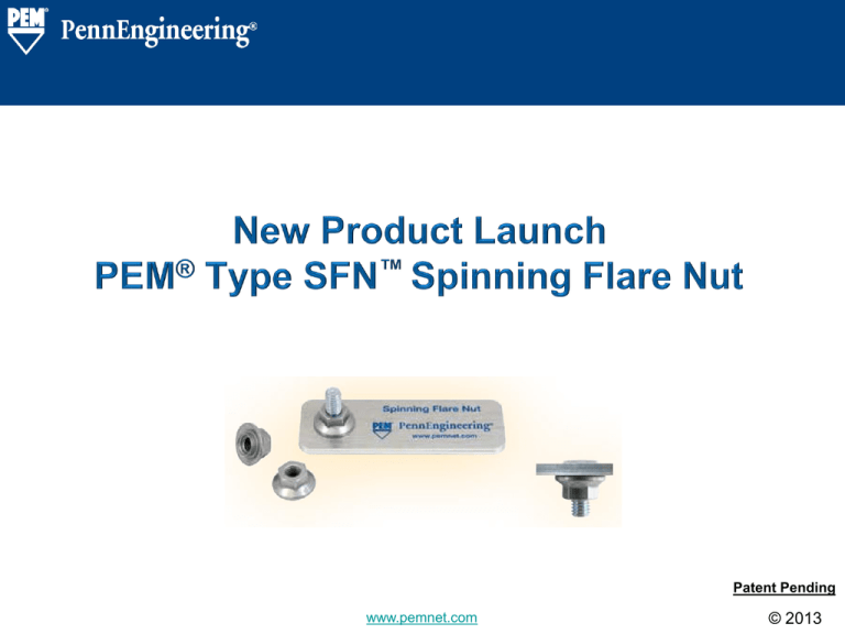
Patent Pending www.pemnet.com ©©2013 2013 PEM® SFN™- Introduction • PEM® Type SFN™ spinning flare nut is a one piece, flanged hex nut that installs by simply pressing it into a properly sized, pre-punched embossed mounting hole. • The nut is permanently captive and still spins freely in the sheet. This allows quick attachment to mating hardware, eliminating much of the need for loose fasteners. • Above the sheet, the part appears identical to standard flanged hex nuts, while on the other side, the part remains flush. • The spinning flare nut eliminates loose hardware such as flange nuts. • When used with a self-clinching stud, all loose hardware is eliminated from the applications. SFN™ Spinning Flare Nut www.pemnet.com 2 ©©2013 2013 PEM® SFN™- Key Benefits Overview SFN™ Sample Panels Opportunity: Loose hardware causes assembly issues as assembler needs to hold panel, nut and driver for the first nut. Spinning Flare Nut Solution: SFN™ spinning flare nut is a hexagonal flange nut that is loosely captivated and free to spin in the sheet. SFN™ Spinning Flare Nut Trademark Key Benefits: • Rotates freely in sheet • It reduces assembly time and cost • There is a reduction in loose hardware (electrical/electronic environment, legislation, design for manufacture) • Installs into any sheet hardness • Nut can be automatically assembled to the panel • It can be used in conjunction with PEM® Self-Clinch stud www.pemnet.com 3 ©©2013 2013 PEM® SFN™- Catalog Offering • Available in M5, M6 & M8 sizes for sheet thickness 1.0 & 1.5mm • As needed, please contact our technical support at techsupport@pemnet.com for your specific application requirements. SFN™ Spinning Flare Nut www.pemnet.com 4 ©©2013 2013 PEM® SFN™- Installation The PEM® SFN™ range of products, will go to market with Pre-emboss of the panel as the default installation process. Characteristics of Pre-emboss: Emboss shape created in panel as first step. Could be part of the bracket stamping operation or as a stand-alone emboss press. Very simple PEMSERTER® tapered flare tool for nut installation. Plating and coatings can be added after emboss stage – reduces risk of damage to coatings in area to be embossed. If your application requires installation into a flat sheet, please contact our technical support at techsupport@pemnet.com as we have tooling options available. www.pemnet.com 5 ©©2013 2013 PEM® SFN™- Installation Tooling & Animation Animation of SFN™ installation is available online in the “nut” category at http://www.pemnet.com/design_info/animation_library.html SFN™ Spinning Flare Nut www.pemnet.com 6 ©©2013 2013 PEM® SFN™- Performance Data • Regulatory compliance information is available in Technical Support section of the PennEngineering website. SFN™ Spinning Flare Nut www.pemnet.com 7 ©©2013 2013 PEM® SFN™- Application Notes Property Class: • The design of SFN™ nuts meets or exceeds proof load requirements of Property Class 8 per ISO 898 Part 2, but because of their unique design they are not marked with a grade marking. Please contact our technical support at techsupport@pemnet.com for your specific application requirements. Design Intent Nut Thread Engagement: Intent – failure of screw in thread Nut Proof Load Performance: Tensile load of 8.8 stud Nut Hardness: Symbols: M5 SFN –Spinning Flare Nut M6 M8 Exceeds ratio 0.8D. Expected failure of screw in thread. Exceeds ratio 0.8D. Expected failure of screw in thread. Exceeds ratio 0.8D. Expected failure of screw in thread. Meets proof load of 12,140N Meets proof load of 17,200N Meets proof load of 31,800N Does not exceed Vickers hardness (HV) 353. Not marked as property class. Torque-Tension Behaviour: • Because of the concave flange the effective friction radius for the nut face is larger than typical resulting in a larger than typical nut factor or “K” value. For joints in which the induced preload is critical, torque-tension studies simulating actual joint conditions are recommended to determine the appropriate tightening torque. Samples of type SFN™ nuts are available for testing. SFN™ Spinning Flare Nut www.pemnet.com 8 ©©2013 2013 PEM® SFN™- Solution – OEM Customer Application SFN™ Benefit • Assembly time reduction & cost • Reduction in loose hardware • Automated assembly of nut to bracket • Improved performance SFN™ Cost Comparison Overview Customer uses loose nuts to assemble supporting brackets. These range from 1.5 – 2.0mm steel both electroplated and KTL painted. This causes assembly issues as person needs to hold bracket, nut and driver for the first nut. Project to design a captive nut which is free to spin. SFN™ Spinning Flare Nut Assembly Cost Fastener cost Loose nut Clinch Installation Method www.pemnet.com 9 © 2013 PEM® SFN™- Solution - Process Cost Saving Process Cost Saving Operator tightens the nut using the driver 0.4 0.35 0.3 € 0.25 0.2 0.15 0.1 Annual Assembly Process Cost Saving Operator picks up power driver 5s 4s 5s -23% 3s 2s 4s 4s Operator places loose nut onto stud and starts to screw down the nut Operator picks up loose nut Process time saving : 5 seconds per nut 4s 0.05 3s 3s Cost - Current Solution Cost - PEM Solution Operator places bracket over stud 0 SFN™ Spinning Flare Nut Assembly Rate $79 / hr = $0.0222 / second Operator picks up bracket www.pemnet.com Process Cost Saving : $0.1065 per nut (Highlighted in Red Text) 10 © 2013 PEM® SFN™- Bulletin SFN™ Spinning Flare Nut www.pemnet.com 11 ©©2013 2013

