Audio
advertisement

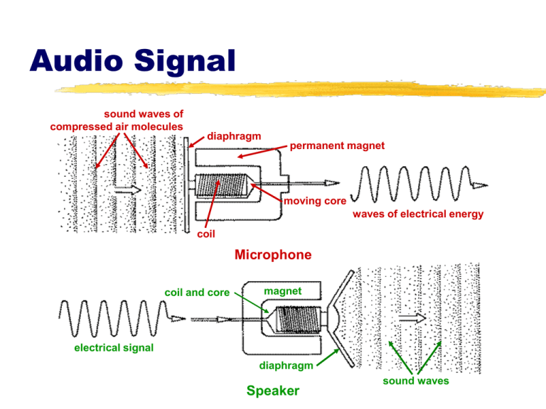
Audio Signal sound waves of compressed air molecules diaphragm permanent magnet moving core waves of electrical energy coil Microphone coil and core magnet electrical signal diaphragm Speaker sound waves Microphones Mics are classified by either: their generating element (transducer) dynamic condenser (electret) ribbon (velocity) their pickup pattern omnidirectional cardioid or unidirectional Generating Elements Transducers output voltage polymer film diaphragm diaphragm impedance converter spacer output voltage magnet voice coil permanently charged electret coating perforated back plate magnetic structure Dynamic Microphone Element Condenser Microphone Element Performance Characteristics of Mic Transducers Dynamic mics durable, have good sound quality Condenser mics excellent sound (good frequency response), require a power source, are somewhat fragile Ribbon mics produce warm sound (excellent frequency response), are extremely fragile Dynamic and Condenser Mic Pros and Cons Dynamic Mic Advantages Condenser Mic Advantages Rugged Lower Cost No Power Required More Sensitive Better Audio Quality Can Be Extremely Small Dynamic Mic Disadvantages Condenser Mic Disadvantages Lower Sensitivity and Power Output Larger and Heavier Slower Response Time Not the Best Choice for Maximum Audio Quality Higher self-noise More Fragile More Expensive Prone to Weather Problems and RF Interference Omnidirectional Pickup Pattern Omnidirectional Pickup Pattern Cardioid Pickup Pattern Cardioid Pickup Pattern Hypercardioid Pickup Pattern Connectors XLR connectors phono plug RCA phone plug mini plug Audio Mixer Select and amplify the incoming sound signals. Control the volume of the various inputs. Mix or combine and balance two or more incoming sound signals. Mixer Inputs Each input module requires that you select either the mic or line input. Mixer Output/VU Meter The mixed and qualityprocessed signal is then routed to the output, sometimes called line-out. Volume Unit (VU) Meters Analog VU Meters VU meters measure the volume units, the relative loudness of amplified sound. Digital VU Meters Calibration An audio system is calibrated when all VU meters respond in the same way to a specific audio signal—the control tone. Here the line-out of the audio mixer is calibrated with the input (recording level) of the VTR. Both VU meters show the same value. Mixing Control—Analog Audio 100% 60% Create proper balance of sound. Keep VU meter(s) in range between 60100% (-5 to 0). VU above 100% distorts VU below 60% sounds weak and may introduce noise into the audio signal. “Riding the gain” means adjusting the input faders to maintain optimal level and balance. Digital Audio Display Stereo meters Calibration—Digital Audio Stereo meters Display Contrast control Left Tab Scroll button [F1]–[F4] buttons Right Tab Scroll button Digital sound is especially susceptible to overmodulation. You should therefore set the audio levels somewhat lower than for analog sound. To calibrate our digital console feed a -12db tone. That is the optimal level for Final Cut Pro. Mixing Control—Digital Audio Display Left Tab Scroll button [F1]–[F4] buttons Digital sound is especially susceptible to overmodulation. You should therefore set Stereo the audio levels meters somewhat lower than for analog sound. Contrast Set the input faders control at a maximum of -15 to -12db rather than 0db. “Riding the gain” means adjusting the Right Tab Scroll button input faders to maintain optimal level and balance.


