Inverting - Discovery Owners Association
advertisement
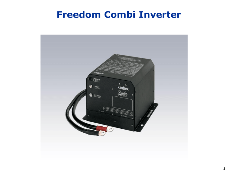
Freedom Combi Inverter 1 Inverter Power Diagram Generator AC1 20A = All Other Inverter Loads AC2 15A = Microwave Main Power Panel Shore Power 30 Amp 115V AC Input Inverter Reset Breaker 458 Inverter 115V Transfer Switch AC1 115V Non-Inverter Charge 115V Loads Aux Start Relay Chassis Battery BCC 300 A Fuse AC2 Invert To 12v Loads Thru Disconnect Switch in BCC 2 Xantrex 458/(Combi 10) Inverter Charger • Charger – 3 stage temperature controlled • Bulk charge • Constant 100 amps DC charging current (50 amps) • Most of the energy is restored to the battery • Takes 21 amps AC to develop this charge current (11 amps) • Acceptance charge for wet cell batteries • Begins when voltage reaches 14.4v @70deg (Cool) • 90 deg = 14.0 (Warm) • 50 deg = 14.8 • Continues to apply constant voltage until • Charge Current decreases to 15 amps (5 amps) • One hour timer expires • Float charge for wet cell batteries • Maintains voltage of 13.5v @70 deg (Cool) • 90 deg – 13.1 (Warm) • 50 deg = 13.9 3 458 Multi-Stage Charging BULK 100 amps ACCEPTANCE • BULK: FLOAT 14.2 volts 13.3 volts Voltage (V) Current (I) 15 amps or 1 hour TIME V O L T A G E Replaces 70-80% of the battery’s capacity at fastest possible rate • ACCEPTANCE: Replenishes remaining 20-30% of battery capacity • FLOAT: Charger voltage is held constant. Replaces battery selfdischarge and powers other DC loads connected to the battery 4 Basic Remote Control Can be used with Freedom 458 or Combi Inverters 5 Combi Remote Control Cannot be used with Freedom 458 Inverters 6 Reading the Remote - Charging • • • • AC IN - will be lit. DC AMPS - Drops following the charge cycle. DC VOLTS - Follows the charge cycle BATTERY STATE - Indicates stage of charge cycle Left = Bulk, Middle = Acceptance, Right = Float 7 Reading the Remote - Inverting • • • • AC IN - will NOT be lit. DC AMPS - Varies with load demand. DC VOLTS - Drops as battery is consumed BATTERY STATE - Indicates Approximate Status of batteries. Left = Recharge Needed, Middle = OK, Right = Full 8 Remote Control Functions • Equalizing Charge –intentional overcharging • Removes sulfate from battery plates • Brings each cell to same voltage and specific gravity • Mixes electrolyte • Wet Cell ONLY • Start with full charge and proper water level • Use Disconnect switch to isolate loads to prevent damage due to high voltage • 16.3 v, variable based on temperature • Timed 8 hour cycle 9 Power Sharing • Your Charger is an AC load • Uses more power than TV or Microwave • Charging power consumption is variable • Purpose • Sets the maximum limit of power consumption • Benefits • Automatically reduces charger’s consumption • Allows other AC loads on inverter circuit to run • Prevents tripping & overloading of shorepower breaker 10 Using the Remote - Power Sharing • Check setting every time you hook up • Set to size of your shorepower connection • Default is 30 amps • If breaker trips, reduce setting • Reducing power sharing reduces charger output • But, increases time needed to complete charging 11 Battery Control Center • Location • In the Electrical Bay • Purpose • Disconnect chassis and coach batteries from their loads • Control ignition switched loads • Controls paralleling of chassis and coach batteries for Charging and Auxiliary Starting • Protects various circuits with fuses and breakers 12
