CASA Doppler Radar Network - Electrical and Computer
advertisement
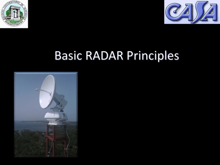
Basic RADAR Principles Prof. Sandra Cruz-Pol, Ph.D. Electrical and Computer Engineering UPRM What is a Radar? radio detection and ranging How does a radar work? Light is an electromagnetic wave. Microwaves = have air wavelengths in the mm – cm scales with frequencies in the Giga Hertz [GHz] range Radar Bands Electromagnetic Spectrum Microwave Remote Sensing • Percentage transmission thought the earth’s atmosphere, along the vertical direction, under clear sky conditions. Cloud and Precipitation Remote Sensing • Atmospheric gases absorption spectrum at the ground in various humidity conditions indicated by the specific humidity values. Types of Doppler Radar • Continuous Wave (CW) – Simple – No range information • Frequency Modulated CW, (FMCW) – Fine range resolution – Artifacts from target motion • Pulse Doppler – Range and Doppler – No artifacts (except when pulse compression used) We will see that Radars work by… Transmitting microwave pulses…. and measuring the … •Time delay (range) •Amplitude •Polarization •Frequency … of the microwave echo in each range gate Compare to: Acoustic Echo-location hello Acoustic Echo-location hello Acoustic Echo-location hello distance Hi !! Hi !! time t = 2 x range / speed of sound Example: range = 150 m Speed of sound ≈ 340 meters/second t = 2 X 150 / 340 ≈ 1 second RADAR Echolocation (RADAR ~ RAdio Detection And Ranging) “Microwave Echo-Location” Tx Rx Microwave Transmitter Receiver Target Range Tx Rx time t = 2 x range / speed of light measure t, then determine Range Example: t = .001 sec Speed of light = c = 3x10⁸ meters/second Range = .001 x 3x108 / 2 = 150,000 m = 150 km We will see that Radars work by… Transmitting microwave pulses…. and measuring the … •Time delay (range) •Amplitude •Polarization •Frequency … of the microwave echo in each range gate Pulse Doppler Radar Unambiguou s Range c cT S R max 2 PRF 2 Range Resolution Top View: 2D Range Resolution ct DRr = 2 q Azimuth Range Resolution DRa = R × q DCAS advantages • Elimination of multiple echoes Radar 1 (Area A) A&B Radar 2 (Area B) False Echo Unambiguous range of 1 radar •Example illustrates DCAS method for identifying real targets and false targets that are aliased in range DCAS advantages (cont) DX • Resolution optimization Target Range gate Beam Radar 1 Radar 2 Has signal Has signal New resolution: Dx’ Dy’ DR We will see that Radars work by… Transmitting microwave pulses…. and measuring the … •Time delay (range) •Amplitude •Polarization •Frequency … of the microwave echo in each range gate Polarization Describes the way the electric field of the wave moves through space as seen from behind along time. • V = vertical lineal • H = Horizontal lineal Sizes for cloud and rain drops Raindrops symmetry Differential Reflectivity Zdr Polarimetric radars, also called dual-pol radars, transmit radio wave pulses that have both H and V orientations. [NOAA] TropiNET radars are the first Polarimatric Doppler radars in PR. Reflectivity Factor, Z • Is defined as Z D 6 N ( D ) dD so that vc 5 4o 2 | Kw | Z • And expressed in dBZ to cover a wider dynamic range of weather conditions. dBZ 10 log Z vc 10 12 5 4 where is in cm 2 | Kw | Z o -1 and 28 Z is expressed 6 in mm /m 3 WHAT VARIABLES ARE MEASURED w/ Dual-pol radar? • Differential Reflectivity –ratio of the reflected H & V power returns. Indicator of drop shape & good estimate of average drop size. • Linear Depolarization Ratio –ratio of a V power return from a H pulse or a H from V. indicator of regions where mixtures of precipitation types occur. • Specific Differential Phase –returned phase difference between the H V pulses caused by the difference in the number of wave cycles (or wavelengths) along the propagation path for horizontal and vertically polarized waves. It’s a "propagation effect.” very good estimator of rain rate. Benefits of polarimetric radars Meteorologists: • can significantly improve the accuracy of the estimates of amounts of precipitation • can tell the difference between very heavy rain and hail, which will improve flash flood watches and warnings • can identify types of precipitation in winter weather forecasts, improving forecasts of liquid water equivalent or snow depth • is more accurate than conventional radar, saving the forecasters the step of having to verify radar data • can contribute to increased lead time in flash flood and winter weather hazard warnings. Hydrologists: • provides critical rainfall estimation information for stream flow forecasts and river flooding Raindrop shapes Average within sample volume We will see that Radars work by… Transmitting microwave pulses…. and measuring the … •Time delay (range) •Amplitude •Polarization •Frequency … of the microwave echo in each range gate Doppler Effect Target Radial Velocity Frequency ft Frequency ft+ fd In Weather radars, the Doppler frequency shift, is caused by the motion of the cloud and precipitation particles Target Radial Velocity Frequency ft Frequency ft+ fd Zero Velocity for “Crossing Targets” Frequency ft Doppler Frequency Frequency ft+ fd fd 2vr t QPE – Quantitative Precipitation Estimation 0.1 mm/hr 1 mm/hr 15 mm/hr 100 mm/hr >150 mm/hr Radar reflectivity (intensity) Doppler effect: shows vortex Cloud and Precipitation Remote Sensing Type of data collected by the millimeter-wave radar. • Observations were made through the melting region of a stratiform cloud previously named “bright band” because of a systematic maximum of echo intensity observed just below the 0º isotherm. Source: Dr. Steve Sekelsky 2004 Melting Layer at Mayaguez-Jun2011 (data from Doppler Pol radar at CID UPRM) Radar equation for Meteorology • For weather applications Pr Pt G 2 o 3 4 2 o R 4 R e Pr vV Pt G c p e 2 o 2 32 4 R o • for a volume 2 o 2 2 2 v g e c ep dr R c p V 2 2 2 43 Radar Equation • For power distribution in the main lobe assumed to be Gaussian function. Pt G o oq o o c p L r 2 Pr 2 1024 ln 2 L e 2 L v R 2 where, v radar reflectivi ty and L r receiver And the two - way atmospheri 2 2 losses c losses are defined here as 2 44 Radar Equation P Pt G o oq o o c r Pr dB Pt dB 2G dB o 20 log( o ) 10 log( q o rad 2 2 p v 2 1024 ln 2 L atm L rec R 2 ) 10 log( o rad 2 10 log ) p 10 log 10 log c 10 log L rec 20 log L atm 10 log( 1024 ln 2 ) 20 log R 2 Pr dB Pt dB 10 log p 10 log R dB c 20 log R For calibrated target RcdB=radar constant (including atmospheric attenuation) 45 References • The COMET project [http://www.comet.ucar.edu/] • NASA TRMM • NCAR (National Center for Atmospheric Research) - University Corporation for Atmospheric Research (UCAR) • NOAA http://www.nssl.noaa.gov/research/radar/dualpol.php • NOAA Educational Page [http://www.nssl.noaa.gov/edu/ideas/radar.html] • Dave McLaughlin Basics of Radars presentation • NWS [http://www.crh.noaa.gov/fsd/soo/doppler/doppler.htm] • http://www.radartutorial.eu/07.waves/wa04.en.html
