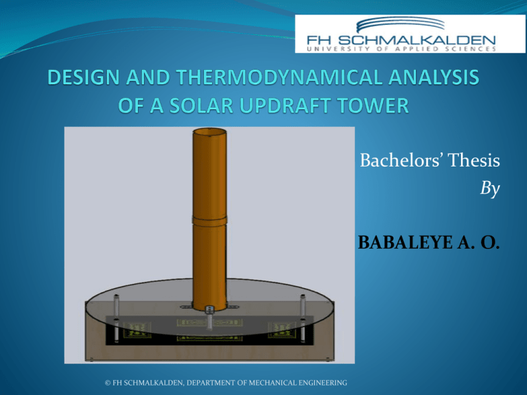
design and thermodynamical analysis of a solar updraft
advertisement

Bachelors’ Thesis By BABALEYE A. O. © FH SCHMALKALDEN, DEPARTMENT OF MECHANICAL ENGINEERING CONTENTS Introduction Seguence Of Operation Alternate Practical Applications Thermodynamics of the Robust Design Turbine Unit Design Humidity and Humidification Effects Results Recommendation © FH SCHMALKALDEN, DEPARTMENT OF MECHANICAL ENGINEERING 2 Introduction Solar collector traps sun radiation to warm air in a greenhouse-like membrane. The energy inherent in atmospheric air is harnessed to drive a turbine. The solar tower serve as an adiabatic duct and works according to the ”chimney effect”. Source: MEF © FH SCHMALKALDEN, DEPARTMENT OF MECHANICAL ENGINEERING 3 Sequence Of Operation 𝑇𝑜 𝑇𝑢 © FH SCHMALKALDEN, DEPARTMENT OF MECHANICAL ENGINEERING 4 Alternate Practical Applications Agricultural sustainability. o Social benefit Enironmental safety improvement. Co-generation purpose. o Economic feasibility © FH SCHMALKALDEN, DEPARTMENT OF MECHANICAL ENGINEERING 5 Thermodynamics of the Robust Design Energy Balance; Chimney effect: -𝑃 = 𝑚[ ℎ𝑜 − ℎ𝑢 + gH] Optimum Air Mass Flow: 𝑚𝑜𝑝𝑡 = 𝐶𝑇1𝑢 2 2 − 𝑤𝑢 2 + 2 2 3 − (𝐾𝑇𝑢 + 𝑔𝐻) Desired Reversible Performance: 𝑃 = 𝐶𝑇1𝑢 Desired Irreversible Performance: 𝑃 = 𝐻 0 𝑤𝑜 2 3 − (𝐾𝑇𝑢 + 𝑔𝐻) 1 𝐶𝑇𝑢 2 (𝐾𝑇𝑢 +𝑔𝐻) − 3 (1+𝜉) 3 2 3 2 𝑤𝑜2 𝜉𝜌𝑜 2 Chimney Head Loss: ∆𝑃 = 𝜌𝑢 − 𝜌𝑜 𝑔𝛿𝐻 = Humid Air Performance: 𝑃𝜔 = 𝑚 72 𝑅𝑠 𝑇𝑜 − 𝑇𝑢 1 2 + (𝜔1 ℎ𝑔1 − 𝜔2 ℎ𝑔2 ) + 𝑤𝑜2 + © FH SCHMALKALDEN, DEPARTMENT OF MECHANICAL ENGINEERING 6 Turbine Unit Design By the principle of flow continuum; 𝑚1 = 𝑚2 𝜌𝑢 𝐴1 𝑤1 = 𝜌𝑜 𝐴2 𝑤2 Unpertubed state; 𝜌𝑢 = 𝜌𝑜 𝑤1 = 3𝑤2 ; tip-speed ratio 𝐴1 . 3𝑤2 = 𝐴2 𝑤2 𝑑2 = √3. 𝑑1 Source: RRE note © FH SCHMALKALDEN, DEPARTMENT OF MECHANICAL ENGINEERING 7 Humidity and Humidification Effects Humid air is lighter than dry air Humidified air tends to accelerate more than dry air. The updraft and turbulence is higher Humidification lowers the temperature of airstream and energy is lost. At elevated temperatures, humidity will improve the performance. © FH SCHMALKALDEN, DEPARTMENT OF MECHANICAL ENGINEERING 8 Results 1120 900 1100 800 1080 700 Relative Power (KW) (W/m^2) 1060 1040 1020 1000 600 500 Ideal Power 400 Actual Power 300 200 980 100 960 0 940 0 2000 4000 6000 8000 10000 12000 Air Mass Flow (Kg/s) 920 295 300 305 310 Tu (K) 315 320 325 © FH SCHMALKALDEN, DEPARTMENT OF MECHANICAL ENGINEERING 9 600 Po,ideal (KW) 500 400 300 200 100 0 295 300 305 310 315 320 325 Tu (K) 90000.00 80000.00 70000.00 m ̇ (kg/s) 60000.00 50000.00 40000.00 30000.00 20000.00 10000.00 0.00 295 300 305 310 315 320 325 Tu (K) © FH SCHMALKALDEN, DEPARTMENT OF MECHANICAL ENGINEERING 10 1.800 1.600 1.400 50.00 1.200 ηII (%) 60.00 η (%) 40.00 1.000 0.800 0.600 30.00 0.400 20.00 0.200 10.00 0.000 0.00 0.00 0.00 20.00 40.00 60.00 m ̇ (kg/s) 20.00 40.00 60.00 m ̇ (kg/s) 80.00 100.00 Thousand 80.00 100.00 Thousand 1400 1200 9000 1000 Power (KW) 8000 (KW) 7000 6000 5000 4000 800 Humidity Power 600 Ideal Power 400 3000 2000 200 1000 0 273 0 0 5 10 15 20 25 30 293 313 333 Tu (K) ω (%) © FH SCHMALKALDEN, DEPARTMENT OF MECHANICAL ENGINEERING 11 Recommendation Optimization should be directed towards increasing the enthalpy by ensuring ∆𝑇 is as large as possible. The top of the tower can be coned such that external wind flow could aid hot air drag from the tower. Perhaps, a second wind turbine could be coupled at the top of the tower to produce additional updraft. The physical and chemical properties of the heat transfer fluid (such as density, specific enthalpy, moisture content, velocity and mass flow) should be adequately exploited. The solar collector should be of superior quality with high concentration efficiency. Since, it has been validated that, the heat exchanger would transmit heat of higher intensity if its optical properties are advantageous. © FH SCHMALKALDEN, DEPARTMENT OF MECHANICAL ENGINEERING 12 Thank you for listening! © FH SCHMALKALDEN, DEPARTMENT OF MECHANICAL ENGINEERING 13


