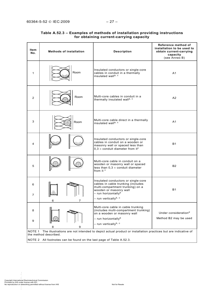
60364-5-52 © IEC:2009 – 27 – Table A.52.3 – Examples of methods of installation providing instructions for obtaining current-carrying capacity Item No. Methods of installation Description Reference method of installation to be used to obtain current-carrying capacity (see Annex B) 1 Room Insulated conductors or single-core cables in conduit in a thermally insulated wall a, c A1 2 Room Multi-core cables in conduit in a thermally insulated wall a, c A2 3 Room Multi-core cable direct in a thermally insulated wall a, c A1 4 Insulated conductors or single-core cables in conduit on a wooden or masonry wall or spaced less than 0,3 × conduit diameter from it c B1 5 Multi-core cable in conduit on a wooden or masonry wall or spaced less than 0,3 × conduit diameter from it c B2 Insulated conductors or single-core cables in cable trunking (includes multi-compartment trunking) on a wooden or masonry wall – run horizontallyb 6 7 6 7 – run vertically b, c Multi-core cable in cable trunking (includes multi-compartment trunking) on a wooden or masonry wall 8 – run horizontallyb 9 8 9 B1 Under consideration d Method B2 may be used – run vertically b, c NOTE 1 The illustrations are not intended to depict actual product or installation practices but are indicative of the method described. NOTE 2 All footnotes can be found on the last page of Table A.52.3. --`,,```,,,,````-`-`,,`,,`,`, Copyright International Electrotechnical Commission Provided by IHS under license with IEC No reproduction or networking permitted without license from IHS Not for Resale – 28 – 60364-5-52 © IEC:2009 Table A.52.3 (continued) Item No Methods of installation Description Reference method of installation to be used to obtain current-carrying capacity (see Annex B) 10 Insulated conductors or single-core cable in suspended cable trunking b B1 11 Multi-core cable in suspended cable trunking b B2 12 Insulated conductors or single-core cable run in mouldings c, e A1 15 Insulated conductors in conduit or singlecore or multi-core cable in architravec, f A1 16 Insulated conductors in conduit or singlecore or multi-core cable in window frames c, f A1 10 11 Single-core or multi-core cables: 20 – fixed on, or spaced less than 0,3 × cable diameter from a wooden or masonry wall c Single-core or multi-core cables: 21 – fixed directly under a wooden or masonry ceiling --`,,```,,,,````-`-`,,`,,`,`,,`--- 22 Single-core or multi-core cables: – spaced from a ceiling 23 Fixed installation of suspended currentusing equipment Copyright International Electrotechnical Commission Provided by IHS under license with IEC No reproduction or networking permitted without license from IHS Not for Resale C C, with item 3 of Table B.52.17 Under consideration Method E may be used C, with item 3 of Table B.52.17 60364-5-52 © IEC:2009 – 29 – Table A.52.3 (continued) Item No. Methods of installation Description Reference method of installation to be used to obtain current-carrying capacity (see Annex B) Single-core or multi-core cables: > < 30 > < ≥ 0,3 De On unperforated tray run horizontally or vertically c, h C with item 2 of Table B.52.17 ≥ 0,3 De > < 31 ≥ 0,3 De Single-core or multi-core cables: E or F On perforated tray run horizontally or vertically c, h NOTE Refer to B.52.6.2 for description --`,,```,,,,````-`-`,,`,,`,`,,`--- > < ≥ 0,3 De > < 32 ≥ 0,3 De E or F Single-core or multi-core cables: On brackets or on a wire mesh tray run horizontally or vertically c, h > < ≥ 0,3 De Single-core or multi-core cables: 33 34 Spaced more than 0,3 times cable diameter from a wall Single-core or multi-core cables: E or F or method G g E or F On ladder c 35 Single-core or multi-core cable suspended from or incorporating a support wire or harness E or F 36 Bare or insulated conductors on insulators G Copyright International Electrotechnical Commission Provided by IHS under license with IEC No reproduction or networking permitted without license from IHS Not for Resale – 30 – 60364-5-52 © IEC:2009 Table A.52.3 (continued) Item No. Methods of installation Description 40 D De e V V 41 D De e V V Single-core or multi-core cable in a building void c, h, i 1,5 D e ≤ V < 5 D e B2 5 D e ≤ V < 20 D e B1 Insulated conductor in conduit in a building void c, i, j, k 1,5 D e ≤ V < 20 D e B2 V ≥ 20 D e B1 42 Single-core or multi-core cable in conduit in a building void c, k 43 Insulated conductors in cable ducting in a building void c, i, j, k 44 V D Dee 45 46 Single-core or multi-core cable in cable ducting in a building void c, k V V D Dee Insulated conductors in cable ducting in masonry having a thermal resistivity not greater than 2 K·m/W c, h, i V V De Single-core or multi-core cable in cable ducting in masonry having a thermal resistivity not greater than 2 K·m/W c Single-core or multi-core cable: 47 D Dee V – in a ceiling void – in a raised floor h, i --`,,```,,,,````-`-`,,`,,`,`,,`--- Copyright International Electrotechnical Commission Provided by IHS under license with IEC No reproduction or networking permitted without license from IHS Reference method of installation to be used to obtain current-carrying capacity (see Annex B) Not for Resale Under consideration The following may be used: 1,5 D e ≤ V < 20 D e B2 V ≥ 20 D e B1 1,5 D e ≤ V < 20 D e B2 V ≥ 20 D e B1 Under consideration The following may be used: 1,5 D e ≤ V < 20 D e B2 V ≥ 20 D e B1 1,5 D e ≤ V < 5 D e B2 5 D e ≤ V < 50 D e B1 Under consideration The following may be used 1,5 D e ≤ V < 20 D e B2 V ≥ 20 D e B1 1,5 D e ≤ V < 5 D e B2 5 D e ≤ V < 50 D e B1 60364-5-52 © IEC:2009 – 31 – Table A.52.3 (continued) Description Reference method of installation to be used to obtain current-carrying capacity (see Annex B) 50 Insulated conductors or single-core cable in flush cable trunking in the floor B1 51 Multi-core cable in flush cable trunking in the floor Item No. Methods of installation 52 53 54 TV TV TV TV ISDN ICT ISDN ICT 52 D Dee B2 Insulated conductors or single-core cables in flush cable trunking c B1 Multi-core cable in flush trunking c B2 53 V Insulated conductors or single-core cables in conduit in an unventilated cable channel run horizontally or vertically c, i, l, n 1,5 D e ≤ V < 20 D e B2 V ≥ 20 D e B1 55 Insulated conductors in conduit in an open or ventilated cable channel in the floor m, n B1 56 Sheathed single-core or multi-core cable in an open or ventilated cable channel run horizontally or verticallyn B1 --`,,```,,,,````-`-`,,`,,`,`,,`--- 57 Copyright International Electrotechnical Commission Provided by IHS under license with IEC No reproduction or networking permitted without license from IHS Single-core or multi-core cable direct in masonry having a thermal resistivity not greater than 2 K·m/W Without added mechanical protection o, p Not for Resale C 60364-5-52 © IEC:2009 – 32 – Table A.52.3 (continued) Item No. Methods of installation 58 Reference method of installation to be used to obtain current-carrying capacity (see Annex B) Description Single-core or multi-core cable direct in masonry having a thermal resistivity not greater than 2 K·m/W C With added mechanical protection o, p 59 Insulated conductors or single-core cables in conduit in masonry p B1 60 Multi-core cables in conduit in masonry p B2 70 Multi-core cable in conduit or in cable ducting in the ground D1 71 Single-core cable in conduit or in cable ducting in the ground D1 72 Sheathed single-core or multi-core cables direct in the ground D2 – without added mechanical protection q --`,,```,,,,````-`-`,,`,,`,`,,`--- Copyright International Electrotechnical Commission Provided by IHS under license with IEC No reproduction or networking permitted without license from IHS Not for Resale 60364-5-52 © IEC:2009 – 33 – Table A.52.3 (continued) Item No. Description Reference method of installation to be used to obtain current-carrying capacity (see Annex B) Sheathed single-core or multi-core cables direct in the ground D2 Methods of installation 73 – with added mechanical protection q a The inner skin of the wall has a thermal conductance of not less than 10 W/m 2 ·K. b Values given for installation methods B1 and B2 in Annex B are for a single circuit. Where there is more than one circuit in the trunking the group reduction factor given in Table B.52-17 is applicable, irrespective of the presence of an internal barrier or partition. c Care shall be taken where the cable runs vertically and ventilation is restricted. The ambient temperature at the top of the vertical section can be increased considerably. The matter is under consideration. --`,,```,,,,````-`-`,,`,,`,`,,`--- d Values for reference method B2 may be used. e The thermal resistivity of the enclosure is assumed to be poor because of the material of construction and possible air spaces. Where the construction is thermally equivalent to methods of installation 6 or 7, reference method B1 may be used. f The thermal resistivity of the enclosure is assumed to be poor because of the material of construction and possible air spaces. Where the construction is thermally equivalent to methods of installation 6, 7, 8, or 9, reference methods B1 or B2 may be used. g The factors in Table B.52.17 may also be used. h D e is the external diameter of a multi-core cable: - 2,2 × the cable diameter when three single core cables are bound in trefoil, or - 3 × the cable diameter when three single core cables are laid in flat formation. i V is the smaller dimension or diameter of a masonry duct or void, or the vertical depth of a rectangular duct, floor or ceiling void or channel. The depth of the channel is more important than the width. j D e is the external diameter of conduit or vertical depth of cable ducting. l D e is the external diameter of the conduit. m For multi-core cable installed in method 55, use current-carrying capacity for reference method B2. n It is recommended that these methods of installation are used only in areas where access is restricted to authorized persons so that the reduction in current-carrying capacity and the fire hazard due to the accumulation of debris can be prevented. o For cables having conductors not greater than 16 mm 2 , the current-carrying capacity may be higher. p Thermal resistivity of masonry is not greater than 2 K·m/W, the term “masonry” is taken to include brickwork, concrete, plaster and the like (other than thermally insulating materials). q The inclusion of directly buried cables in this item is satisfactory when the soil thermal resistivity is of the order of 2,5 K·m/W. For lower soil resistivities, the current-carrying capacity for directly buried cables is appreciably higher than for cables in ducts. Copyright International Electrotechnical Commission Provided by IHS under license with IEC No reproduction or networking permitted without license from IHS Not for Resale


