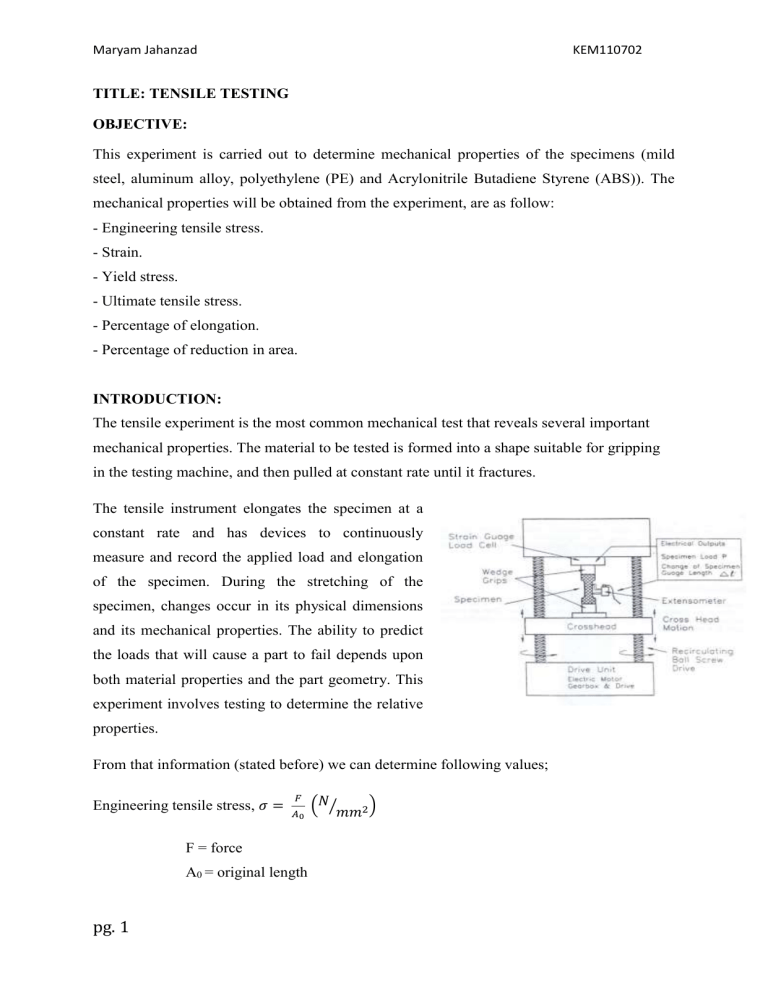
Maryam Jahanzad KEM110702 TITLE: TENSILE TESTING OBJECTIVE: This experiment is carried out to determine mechanical properties of the specimens (mild steel, aluminum alloy, polyethylene (PE) and Acrylonitrile Butadiene Styrene (ABS)). The mechanical properties will be obtained from the experiment, are as follow: - Engineering tensile stress. - Strain. - Yield stress. - Ultimate tensile stress. - Percentage of elongation. - Percentage of reduction in area. INTRODUCTION: The tensile experiment is the most common mechanical test that reveals several important mechanical properties. The material to be tested is formed into a shape suitable for gripping in the testing machine, and then pulled at constant rate until it fractures. The tensile instrument elongates the specimen at a constant rate and has devices to continuously measure and record the applied load and elongation of the specimen. During the stretching of the specimen, changes occur in its physical dimensions and its mechanical properties. The ability to predict the loads that will cause a part to fail depends upon both material properties and the part geometry. This experiment involves testing to determine the relative properties. From that information (stated before) we can determine following values; Engineering tensile stress, 𝜎 = 𝐹 𝐴0 F = force A0 = original length pg. 1 (𝑁⁄𝑚𝑚2 ) Maryam Jahanzad (i) Strain, 𝜀 = KEM110702 𝐿1 − 𝐿0 𝐿0 L1 = length after strain L0 = original length (ii) Yield strength, 𝜎𝑦 = 𝑌𝑖𝑒𝑙𝑑 𝑤𝑒𝑖𝑔ℎ𝑡 𝑜𝑟𝑖𝑔𝑖𝑛𝑎𝑙 𝑐𝑟𝑜𝑠𝑠 𝑠𝑒𝑐𝑡𝑖𝑜𝑛𝑎𝑙 𝑎𝑟𝑒𝑎 (iii)Ultimate/maximum tensile stress, 𝜎𝑚 = (iv) Percentage of elongation = 𝐿1 − 𝐿0 𝐿0 (v) Percentage of reduction of area = (𝑁⁄𝑚𝑚2 ) 𝑚𝑎𝑥𝑖𝑚𝑢𝑚 𝑙𝑜𝑎𝑑 𝑂𝑟𝑖𝑔𝑖𝑛𝑎𝑙 𝑐𝑟𝑜𝑠𝑠 𝑠𝑒𝑐𝑡𝑖𝑜𝑛𝑎𝑙 𝑎𝑟𝑒𝑎 × 100% 𝐴0 − 𝐴1 𝐴0 × 100% A0 = original area A1 = area after stress (a) Tensile Test for metal d A0 L0 A0 a L1 pg. 2 (𝑁⁄𝑚𝑚2 ) Maryam Jahanzad KEM110702 For tensile load and maximum load, it can be obtained from the graph of load (N) versus elongation: (i) Mild Steel Fm Fp Fy Load Elongation Fy = Yield load (N) Fm = maximum load (N) Fp = Tensile strength (N) (ii) For aluminum alloy or any element which do not have fixed yield strength, the yield strength is obtained using the “0.2% strain offset method”. This is also known as “Tegasan pruf”. The graph is shown below. Fm Fp F0.2% Load Elongation pg. 3 Maryam Jahanzad KEM110702 (b)Tensile Test for plastic Figure shows the plastic specimen before and after deformation A0 L0 before testing A1 L1 Graph of stress-elongation for plastics is illustrated as follow: σy σb MN/m 2 E σy = yield strength σb = Tensile strength pg. 4 Maryam Jahanzad KEM110702 F F A L0 F L F APPARATUS: Specimens: o mild steel o aluminum alloy o polyethylene (PE) o Acrylnitrile Butadiene Styrene (ABS) Universal testing machine marker vernier calipers ruler PROCEDURES: (a) Tensile stress test for metals 1. The diameter, width and original length of the mild steel are measured. 2. 10 lines are marked with 10mm each part by using knife and ruler. 3. The mild steel is clamped in the machine. 4. The machine is then operated automatically. pg. 5 Maryam Jahanzad KEM110702 5. After the mild steel is fractured, its final diameter, width and length are measured. 6. Step 1-5 is repeated using aluminum alloy 7. The way of specimen break is observed. (b) Tensile stress test for plastics 1. The width, breadth, length of the polyethylene (PE) is measured 2. 10 lines are marked with 10mm each part by using marker and ruler. 3. The polyethylene (PE) is clamped in the machine. 4. The machine is then operated automatically. 5. After the polyethylene (PE) is fractured, its final breadth, width and length are measured. 6. Step 1-5 is repeated using Acrylnitrile Butadiene Styrene (ABS) 7. The way of specimen break is observed. PRECAUTIONS: a) Reading of the diameter and length is repeated several times to get the mean. This is to reduce and minimize the parallax error. b) Make sure the specimen is not being interrupt when the load is applied on specimen. c) The specimens are clip tightly on the machine and make sure it is in the correct position in order not to affect the reading. d) Make sure the reading entered in the computer is correct. e) Read the manual on how to use the Universal testing machine before use. pg. 6 Maryam Jahanzad KEM110702 RESULTS AND CALCULATIONS: Specimen Reading First Reading Initial Mild Steel Second Third Average Reading Reading 9.90 9.65 10.00 9.85 5.95 6.35 5.70 6.00 60.00 60.00 60.00 60.00 81.05 79.85 81.05 80.65 9.30 9.40 9.40 9.37 6.70 6.50 6.20 6.47 50.00 50.00 50.00 50.00 64.65 64.40 64.60 64.55 diameter, D0 (mm) Final diameter, D1 (mm) Initial length, L0 (mm) Final length, L1 (mm) Aluminum Initial alloy diameter, D0 (mm) Final diameter, D1 (mm) Initial length, L0 (mm) Final length, L1 (mm) (a) Mild steel From graph, we obtained: Load = 50.00kN Load at 0.2% strain = 26.049 kN Maximum load = 34.290 kN Fracture load = 24.290kN Original area, A0 = 𝜋𝑑0 2 4 =7.62 × 10⁻⁵ 𝑚2 pg. 7 Maryam Jahanzad KEM110702 Engineering tensile stress, 𝜎 = 50×103 7.62×10−5 = 6.56 × 10⁸ 𝑁⁄𝑚𝑚2 Strain, 𝜀 = 80.65− 60 60 = 0.34 34.29×10³ Ultimate stress, σm = 7.62×10−5 =450.0 MPa Percentage of elongation = 80.65− 60 60 × 100% = 0.34 × 100% = 34% Final area, A1 = 𝜋𝑑1 2 = 4 𝜋(6×10⁻³ )2 4 =2.83 × 10⁻⁵ 𝑚2 Percentage decrease in area= 7.62×10⁻⁵ − 2.83×10⁻⁵ 7.62×10−5 = 62.86% pg. 8 × 100% Maryam Jahanzad KEM110702 From the data computed by computer, mild steel has: Ultimate Yield strength, σy/ MPa stress/ tensile strength, σm/ MPa 341.848 450.0 Fracture Strength, σp/ MPa 318.70 Data transferred from the Load – Displacement Graph obtained from computer: mild steel Displacement (mm) Load (kN) Stress (MPa) Strain 0.00 0.00 0.00 0.00 5.00 27.50 360.89 0.08 10.00 28.67 376.25 0.17 15.00 27.00 354.33 0.25 20.00 30.00 393.70 0.33 25.00 31.50 413.39 0.42 30.00 32.55 427.17 0.50 35.00 33.60 440.94 0.58 40.00 33.80 443.57 0.67 45.00 33.90 444.88 0.75 50.00 34.00 446.19 0.83 55.00 33.97 445.80 0.92 68.07 0.00 0.00 1.13 pg. 9 Maryam Jahanzad KEM110702 Graph of stress against strain 600 500 400 stress 300 (MPa) Ряд1 200 100 0 0 0,2 0,4 0,6 strain pg. 10 0,8 1 1,2 Maryam Jahanzad KEM110702 (b) Aluminum alloy From graph, we obtained: Load = 50.00kN Load at 0.2% strain = 13.215 kN Maximum load = 15.710 kN Fracture load = 11.80 kN Original area, A0 = 𝜋𝑑0 2 4 =6.89 × 10⁻⁵ 𝑚2 Engineering tensile stress, 𝜎 = 50×103 6.76×10−5 = 7.26 × 10⁸ 𝑁⁄𝑚𝑚2 Strain, 𝜀 = 64.55− 50 50 = 0.291 Ultimate stress, σm = 15.71×10³ 6.9×10−5 =227.68 MPa Percentage of elongation = 64.55− 50 50 × 100% = 0.291 × 100% = 29.1% Final area, A1 = = 𝜋𝑑1 2 4 𝜋7.082 4 =3.29 × 10⁻⁵ 𝑚2 pg. 11 Maryam Jahanzad KEM110702 Percentage decrease in area= 7.26×10⁻⁵ − 3.29×10⁻⁵ 7.26×10−5 × 100% = 56.82% From the data computed by computer, aluminum alloy has: Yield strength, σy/ Ultimate stress/ tensile strength, σm/ Fracture Strength, σp/ MPa MPa MPa 195.23 227.68 171.18 pg. 12 Maryam Jahanzad KEM110702 Data transferred from the Load – Displacement Graph obtained from computer: aluminum alloy Displacement (mm) Load (kN) Stress (MPa) Strain 0.00 0.00 0.00 0.00 2.50 10.13 146.81 0.05 5.00 14.38 208.41 0.10 7.50 14.75 213.77 0.15 10.00 15.00 217.39 0.20 12.50 15.10 218.84 0.25 15.00 15.25 221.01 0.30 17.50 15.30 221.74 0.35 20.00 15.60 226.09 0.40 22.50 15.65 226.81 0.45 25.00 15.71 227.68 0.50 27.50 15.50 224.64 0.55 31.43 0.00 0.00 0.63 pg. 13 Maryam Jahanzad KEM110702 Graph of strees against strain 300 250 200 stress 150 (MPa) Ряд1 100 50 0 0 0,1 0,2 0,3 0,4 strain pg. 14 0,5 0,6 0,7 Maryam Jahanzad KEM110702 (b) Tensile test for plastics Specimen Reading Second Third Reading Reading 10.28 10.28 10.27 10.28 3.20 3.15 3.20 3.18 50.00 50.00 50.00 50.00 191.00 190.00 188.00 189.7 3.3 3.25 3.25 3.27 1.40 1.55 1.62 1.52 10.33 10.34 10.33 10.33 10.31 10.20 10.20 10.24 49.80 49.80 49.80 49.80 L1 (mm) 49.70 49.90 50.00 49.87 Initial thick, 3.30 3.25 3.25 3.3 3.20 3.15 3.20 3.18 Polyethylene Initial width, (PE) W0 (mm) Final width, First Reading Average W1 (mm) Initial length, L0 (mm) Final length, L1 (mm) Initial thick, T0 (mm) Final thick, T1 (mm) Acrylontrile Initial width, Butadiene W0 (mm) Styrene (ABS) Final width, W1 (mm) Initial length, L0 (mm) Final length, T0 (mm) Final thick, T1 (mm) pg. 15 Maryam Jahanzad KEM110702 Polyethylene (PE) From graph, we obtained: Load = 50.00kN Load at 0.2% strain = 0.498 kN Maximum load = 0.929 kN Fracture load = 0.091 kN Original area, A0 = 𝑡ℎ𝑖𝑐𝑘 × 𝑤𝑖𝑑𝑡ℎ =3.36 × 10⁻⁵ 𝑚2 50×103 Engineering tensile stress, 𝜎 = 3.36×10−6 = 14.87 × 10⁸ 𝑁⁄𝑚2 Strain, 𝜀 = 189.7 − 50 50 = 2.794 Percentage of elongation = 189.7 − 50 50 × 100% = 2.794 × 100% = 279.40% Final area, A1 = 𝑡ℎ𝑖𝑐𝑘 × 𝑤𝑖𝑑𝑡ℎ =4.834 × 10⁻⁶ 𝑚2 Percentage decrease in area= 3.36 ×10⁻⁵ − 4.834×10⁻⁶ 3.36 ×10−5 = 85.61% pg. 16 × 100% Maryam Jahanzad KEM110702 From the data computed by computer, polyethylene has: Yield strength, σy/ MPa 14.818 Ultimate stress/ tensile strength, σm/ MPa 27.638 Fracture Strength, σp/ MPa 2.716 Data transferred from the Load – Displacement Graph obtained from computer: PE Displacement (mm) Load (kN) Stress (MPa) Strain 0.00 0.00 0.00 0.00 10.00 0.92 27.38 0.20 20.00 0.85 25.30 0.40 30.00 0.52 15.48 0.60 50.00 0.50 14.88 1.00 70.00 0.52 15.48 1.40 90.00 0.50 14.88 1.80 110.00 0.50 14.88 2.20 120.00 0.48 14.29 2.40 130.00 0.41 12.20 2.60 140.00 0.34 10.12 2.80 150.00 0.04 1.19 3.00 160.00 0.02 0.60 3.20 pg. 17 Maryam Jahanzad KEM110702 Graph of Stress againts Strain 35 30 25 20 Stress (MPa) 15 10 5 0 0 0,5 1 1,5 2 Strain pg. 18 2,5 3 3,5 Maryam Jahanzad KEM110702 Acrylontrile Butadiene Styrene (ABS) From graph, we obtained: Load = 50.00kN Load at 0.2% strain = 0.965 kN Maximum load = 0.966 kN Fracture load = 0.761 kN Original area, A0 = 𝑡ℎ𝑖𝑐𝑘 × 𝑤𝑖𝑑𝑡ℎ =3.41 × 10⁻⁵ 𝑚2 Engineering tensile stress, 𝜎 = 50×103 3.41×10−5 = 14.67 × 10⁸ 𝑁⁄𝑚𝑚2 Strain, 𝜀 = 49.87 – 49.8 49.8 = 1.4 × 10⁻³ Percentage of elongation = 49.87 – 49.8 49.8 × 100% = 1.4 × 10−3 × 100% = 0.14% Final area, A1 = 𝑡ℎ𝑖𝑐𝑘 × 𝑤𝑖𝑑𝑡ℎ =3.26 × 10⁻⁵ 𝑚𝑚2 Percentage decrease in area= 3.41 ×10⁻⁵ − 3.26×10⁻⁵ 3.41 ×10−5 × 100% = 4.4% From the data computed by computer, Acrylontrile Butadiene Styrene (ABS) has: Yield strength, σy/ MPa 28.475 pg. 19 Ultimate stress/ tensile strength, σm/ MPa 28.514 Fracture Strength, σp/ MPa 22.456 Maryam Jahanzad KEM110702 Data transferred from the Load – Displacement Graph obtained from computer: ABS Displacement (mm) Load (kN) Stress (MPa) Strain 0.00 0.00 0.00 0.00 0.25 0.10 2.93 0.005 0.50 0.25 7.33 0.010 0.75 0.40 11.73 0.015 1.00 0.55 16.13 0.020 1.25 0.74 21.70 0.025 1.50 0.83 24.34 0.030 1.75 0.94 27.57 0.035 2.00 0.93 27.27 0.040 2.25 0.83 24.34 0.045 2.50 0.04 1.17 0.050 3.00 0.04 1.17 0.060 9.75 0.04 1.17 0.196 pg. 20 Maryam Jahanzad KEM110702 Graph of stress against strain 30 25 20 15 stress (MPa) Ряд1 10 5 0 0 -5 pg. 21 0,05 0,1 0,15 strain 0,2 0,25 Maryam Jahanzad KEM110702 DISCUSSION: a) Tensile test for metals Mechanical behaviour Mild Steel Aluminium alloy Yields stress (MPa) 341.848 195.23 Ultimate tensile strength 450.00 227.68 (MPa) Fracture stress (MPa) 318.70 171.18 % Elongation 34% 29.1% 1. Graph stress- strain for mild steel shown its experience a yield load. Whereas, aluminium alloy did not experience a specify yield load. And therefore, “0.2% offset method” is used. 2. From the result, the value of tensile stress, fracture stress and yield load for mild steel is higher than that of aluminium alloy. This means that more force is required to elongate the mild steel. This phenomenon is caused by the composition of the carbon and iron in the mild steel which makes it harder. 3. As mild steel is an alloy that consists of carbon and iron. The atom size of carbon and iron is different. Because of different size of atom, the atom in the mild steel is packed more closely. Besides that, carbon atom (filler atom) is act as resistance for the dislocation. Therefore the sliding of the atomic layer can be minimizing. Grain size atom fills vacancy and interstitial sites so that the iron atoms cannot slide through each other easily. 4. The area under the graph stress- strain represented the energy absorb by the metal to deform. Since the area under graph for mild steel is greater than aluminium alloy, therefore mild steel can absorb more energy. pg. 22 Maryam Jahanzad KEM110702 b) Tensile test for plastics Acrylonitrile Mechanical behaviour Polyethylene (PE) Yields stress (MPa) 14.818 28.475 strength 27.638 28.514 Ultimate tensile Butadiene Styrene (ABS) (MPa) Fracture stress (MPa) 2.716 22.456 % Elongation 279.40% 0.14% 1. From the experiment, the mechanical properties of PE and ABS can be observed. PE experiences large plastic deformation before it breaks. Whereas, ABS experience little plastic deformation before it break. This can be said that PE is more ductile than ABS. 2. From the result obtained, yields stress for ABS is higher than PE. It shows that ABS can afford a higher stress compare to PE before undergoing plastic deformations. Besides that, stress at fracture for ABS also higher than PE. Therefore, ABS is stronger, harder and stiffer compare to PE. CONCLUSION: a) Tensile test for metal In conclusion, mild steel is stiffer, stronger, harder, more ductile and able to undergo high stress before fracture than Aluminum alloy. b) Tensile test for plastic Polyethylene plastic is harder, stiffer and stronger than Acrylontrile Butadiene Styrene (ABS). But Butadiene Styrene (ABS) has higher ductility than Polyethylene plastic (PE). pg. 23 Maryam Jahanzad KEM110702 REFERENCE: 1. Rollason : Metallurgy for Engineering 2. William F.Smith & Javad Hashemi: Foundations of Materials Science and Engineering 4th Edition. 3. Materials Science and Engineering An Introduction, 6th Edition; William D. Callister, Jr. John Wiley & Sons, Inc. Chapter 6 pg. 24
