Control Systems II Tutorial: Frequency-Based Controller Design
advertisement

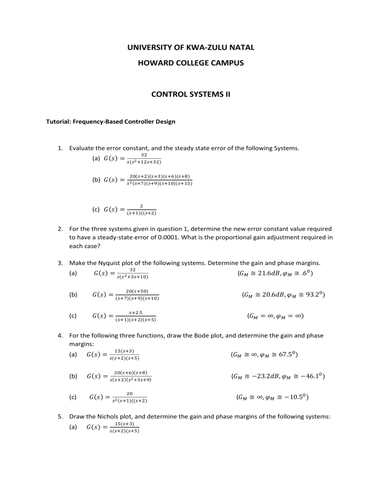
UNIVERSITY OF KWA-ZULU NATAL HOWARD COLLEGE CAMPUS CONTROL SYSTEMS II Tutorial: Frequency-Based Controller Design 1. Evaluate the error constant, and the steady state error of the following Systems. 32 (a) 𝐺(𝑠) = 𝑠(𝑠2 +12𝑠+32) 20(𝑠+2)(𝑠+3)(𝑠+6)(𝑠+8) (b) 𝐺(𝑠) = 𝑠2 (𝑠+7)(𝑠+9)(𝑠+10)(𝑠+15) 2 (c) 𝐺(𝑠) = (𝑠+1)((𝑠+2) 2. For the three systems given in question 1, determine the new error constant value required to have a steady-state error of 0.0001. What is the proportional gain adjustment required in each case? 3. Make the Nyquist plot of the following systems. Determine the gain and phase margins. 32 𝑠(𝑠2 +3𝑠+10) (a) 𝐺(𝑠) = (b) 𝐺(𝑠) = (c) 𝐺(𝑠) = (𝑠+1)(𝑠+2)(𝑠+5) 20(𝑠+50) (𝑠+7)(𝑠+9)(𝑠+10) 𝑠+2.5 (𝐺𝑀 ≅ 21.6𝑑𝐵, 𝜑𝑀 ≅ .60 ) (𝐺𝑀 ≅ 20.6𝑑𝐵, 𝜑𝑀 ≅ 93.20 ) (𝐺𝑀 = ∞, 𝜑𝑀 = ∞) 4. For the following three functions, draw the Bode plot, and determine the gain and phase margins: 15(𝑠+3) (𝐺𝑀 ≅ ∞, 𝜑𝑀 ≅ 67.50 ) 20(𝑠+6)(𝑠+8) (𝐺𝑀 ≅ −23.2𝑑𝐵, 𝜑𝑀 ≅ −46.10 ) (a) 𝐺(𝑠) = 𝑠(𝑠+2)(𝑠+5) (b) 𝐺(𝑠) = 𝑠(𝑠+2)(𝑠2 +3𝑠+9) (c) 𝐺(𝑠) = 𝑠2 (𝑠+1)((𝑠+2) 20 (𝐺𝑀 ≅ ∞, 𝜑𝑀 ≅ −10.50 ) 5. Draw the Nichols plot, and determine the gain and phase margins of the following systems: (a) 15(𝑠+3) 𝐺(𝑠) = 𝑠(𝑠+2)(𝑠+5) 20(𝑠+6)(𝑠+8) 𝑠(𝑠+2)(𝑠2 +3𝑠+9) (b) 𝐺(𝑠) = (c) 𝐺(𝑠) = 𝑠2 (𝑠+1)((𝑠+2) 20 𝐾 6. The system 𝐺(𝑠) = 𝑠(𝑠+50)(𝑠+12) is used in unity feedback. Using frequency based methods: (i) Find the value of K required to yield a closed-loop response of 20%. (K=194,200) (ii) Design a lag controller to reduce the steady-state error by a factor of 10. ( 𝐺𝐶 𝑙𝑎𝑔 (𝑠) = 0.0691(𝑠+2.04) 𝑠+0.141 ) 100𝐾 7. It is required to compensate the system 𝐺(𝑠) = 𝑠(𝑠+100)(𝑠+36) , so that the closed-loop response yields a peak time 𝑡𝑝 = 0.1 𝑠𝑒𝑐, a steady-state error constant 𝐾𝑉 = 40 and a damping factor 𝜉 = 0.456 (20% overshoot). Design the lead controller required. Add a phase 𝑠+25.3 adjustment of 100 . (𝜑𝑑 = 48.10 , 𝜑𝑚𝑎𝑥 = 24.10 , 𝛽 = 0.42, 𝐺𝐶 𝑙𝑒𝑎𝑑 (𝑠) = 2.38 𝑠+60.2 ). 8. For the system 𝐺(𝑠) = 𝐾 , 𝑠(𝑠+50)(𝑠+12) 𝑇𝑠 = 0.2 𝑠𝑒𝑐. ( 𝐺𝐶 𝑙𝑒𝑎𝑑 (𝑠) = design a lead controller for 𝐾𝑉 = 50, %𝑂𝑆 = 20, and 2.27(𝑠+33.2) 𝑠+75.4 ) 𝐾 𝑉 9. For 𝐾𝑉 = 12/𝑠𝑒𝑐, design a lead controller for the system 𝐺(𝑠) = 𝑠(𝑠+1) such that the resulting closed-loop system has a phase margin of 400 . Adjust the resultant angle by +50 . (𝜑𝑚𝑎𝑥 = 300 , 𝐺𝐶 𝑙𝑒𝑎𝑑 (𝑠) = 0.337𝑠𝑠+1 0.125𝑠+1 ) 𝐾 10. Design a double lead controller for the system 𝐺(𝑠) = 𝑠2 (0.2𝑠+1) for an acceleration error constant 𝐾𝑎 = 10 and a phase margin of 350 . Why is a double lead control network required in this particular problem? Add a 140 phase adjustment. (K=10, 𝜑𝑚𝑎𝑥 = 35 − (−33) + 14 = 820 . Divide the 82 degrees into 41 degrees each. For (0.358𝑠+1)2 0.358𝑠+1 ∗ each of the lead controllers, 𝜑𝑚𝑎𝑥 = 410 , 𝛽 = 0.2. 𝐺𝐶1 𝑙𝑒𝑎𝑑 = 0.077𝑠+1 ; 𝐺𝐶 𝑙𝑒𝑎𝑑 = (0.077𝑠+1)2 ) 𝐾 11. Design a lag controller for 𝐺(𝑠) = 𝑠(𝑠+1)(𝑠+4) so that the closed-loops system has the following performance. The tolerance band is 5% (not the usual 2%). Damping factor 𝜉 = 0.4 3 Settling time 𝑡𝑠 = 10 𝑠𝑒𝑐. (For a 5% tolerance band, 𝑡𝑠 = 𝜉𝜔 𝑛 Velocity error constant 𝐾𝑉 ≥ 5𝑠𝑒𝑐 Use an angular adjustment of 120 . ). −1 ( 𝜑𝑑 = 430 , 𝜔𝑏 = 1.02 𝑟𝑎𝑑𝑠𝑒𝑐 −1 , 𝜑𝑚𝑎𝑥 = 550 , 𝜔𝑐 = 0.522 𝑟𝑎𝑑𝑠𝑒𝑐.−1 )


