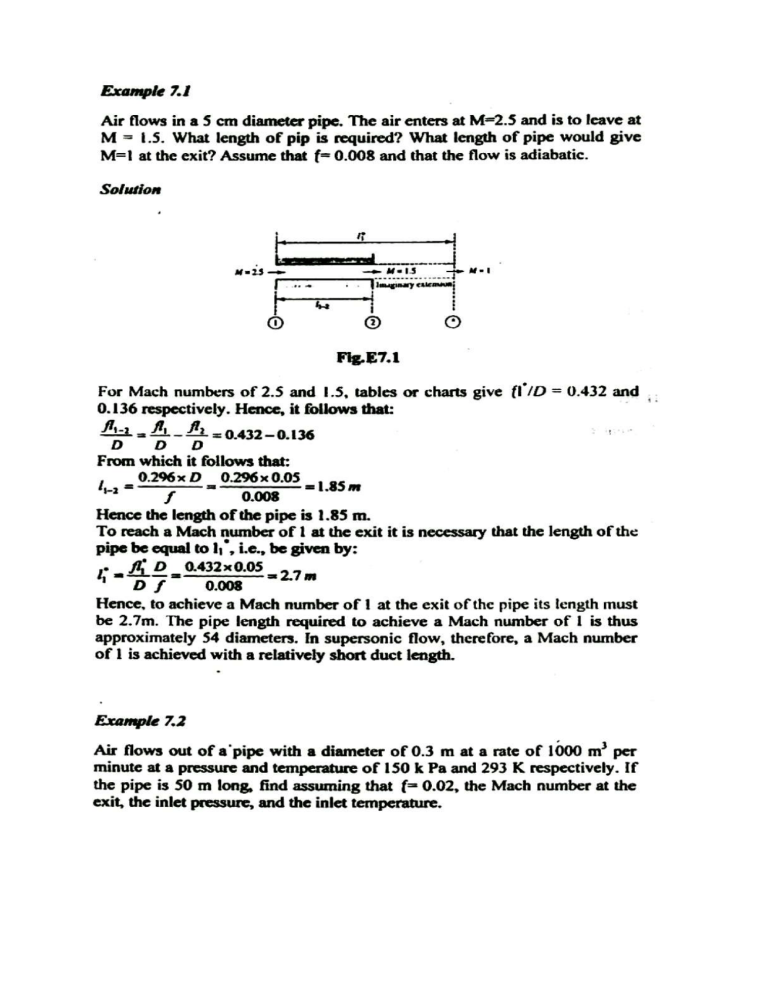
Example 7.3 Example 7.4 Air (γ = 1.4) flows into a constant-area insulated duct with a Mach number of 0.20. For a duct diameter of 1 cm and friction coefficient of 0.02, determine the duct length required to reach Mach 0.60. Determine the length required to attain Mach 1. Finally if an additional 75 cm is added to the duct length needed to reach Mach 1, while the initial stagnation conditions are maintained, determine the reduction in flow rate that would occur. Example 7.5 Air (γ = 1.4 and R = 0.287 kJ/kg · K) enters a constant-area insulated duct with a Mach number of 0.35, a stagnation pressure of 105 kPa, and stagnation temperature of 300 K. For a duct length of 50 cm, duct diameter of 1 cm, and friction coefficient of 0.022, determine the air force on the duct wall. Example 7.6 For the flow of air (γ = 1.4 and R = 0.287 kJ/kg · K) from the reservoir at 650 kPa and 1000 K shown in Figure, assume isentropic flow in the convergent divergent nozzle and Fanno flow in the constant-area duct, which has a length of 20 cm and a diameter of 1 cm. The area ratio A2/A1 of the C-D nozzle is 2.9. Take the friction factor to be 0.02. (a) Find the mass flow rate for a back pressure of 0 kPa. (b) For part (a), find the pressure at the exit plane of the duct. (c) Find the back pressure necessary for a normal shock to occur at the exit plane of the nozzle (2). (d) Find the back pressure necessary for a normal shock to appear just downstream of the nozzle throat (1). Example 7-7: Air (γ = 1.4 and R = 0.287 kJ/kg · K) flows through a converging diverging nozzle with area ratio of 2.9 (Figure ), which exhausts into a constant area insulated duct with a length of 50 cm and diameter of 1 cm. If the system back pressure is 50 kPa, determine the range of reservoir pressures over which a normal shock will appear in the duct. Let f = 0.02 in the duct. Example 7-8 A converging-diverging nozzle with area ratio of 3.2 (Figure) exhausts air (γ = 1.4 and R =0.287 kJ/kg · K) into a constant-area insulated duct with a length of 50 cm and diameter of 1 cm. If the reservoir pressure is 500 kPa, determine the range of back pressures over which a normal shock will appear in the duct (f = 0.02). MENOUFIYA UNIVERSITY Mech. power eng. Dept GAS DYNAMICS Faculty of Engineering 2017-2018 rd 3 year M.P.E Sheet (7) 1-a) Estimate the maximum flow rate of air (kg/sec) which can flow through the passage shown, assuming that the friction coefficient of the duct is 0.02 (b) For what range of back pressure will this maximum flow rate by a achieved? 2- Air flows subsonically in an adiabatic 250 mm diameter duct. The Darcy friction factor is 0.024, what length of the duct is necessary to accelerate the flow from Mi 0.1 to M2=0.5? What additional length will accelerate it to M3 = 1.0? - Assume that at Mi =0.1 the pressure and temperature were 7 bar and 60°C respectively, compute at the section in which M2 = 0.5, P2, T2, V2 and P02 Compute also the net force of the fluid on the pipe. 3- Air enters a 30 mm diameter duct at P0 = 2 bar. T0 = 500 K and V] = 100 m/s. The Darcy friction factor is 0.02. Compute: - the maximum duct length for, these conditions the mass flux if the duct length is 15m and - the reduced mass flux for duct length of 30 m. 4-A convergent – divergent nozzle constant area duct a system is connected to a reservoir containing air with a stagnation Po=700 kPa. The exit to throat area ratio of the nozzle is 3, the constant area duct is 6 m long and 0.3 m in diameter with a friction coefficient of 0.02. Determine the range of back pressure for which a normal shock wave will stand in duct. 5-An apparatus that is used for determining Darcy friction factor with air flow through a pipe consists of a reservoir connected to a convergent-divergent nozzle which in turn connected to the pipe. The nozzle has a throat diameter of 0.6 cm and the diameter of the pipe, which is well insulated, is 0.9 cm. In one experiment, the pressure and temperature in the reservoir are 1.7 MPa and 40°C respectively and the pressure a distance of 0.15 m from the inlet to the pipe is 340 kPa. Calculate the Darcy friction factor in the pipe. Assume that the Flow in the nozzle is isentropic. 6- A nozzle having an exit to throat area of ratio of 4.23 is connected to a Large air reservoir where the pressure and temperature are maintained at Po= 9.81 bar and T0= 400k. The nozzle discharges into a pipe of diameter 2.5 cm that equal to the exit diameter of the nozzle. The pipe discharge into a space where the pressure remains at 1.96 bar the pipe length can be adjusted for flow analysis. Determine:- a) The length of the pipe so that a shock wave would be maintained at exits section of the nozzle, the exit pipe velocity and pressure and force required to holed the system place. b) The length of the pipes so that a shock would be stationed 0.5 m upstream of the pipe exit. What is the static pressure reading at a quarter pipe length stream nozzle exit? c) Draw the pressure distribution a long the pipe for a & b, assume a Darcy friction Coefficient 0.02 for subsonic. 7-A convergent – divergent nozzle having a throat diameter of 1.54 cm receives air from a large tank at a temperature of 400k and discharge it through a pipe of long 125 cm and diameter 4 cm. The pipe discharge into atmosphere. Air jet leaving the pipe impacts on a large plate. Assume friction coefficient of pipe is 0.012. a)-Find the pipe exit pressure and velocity for the following tank pressure: 1)- 7 kg/sq. cm. 2) 10 kg/sq.cm., 3) 35 kg/sq.cm. b)- Which the above tank pressure result in positioning the shock inside the duct system. c)-Determine the force acting on the plate for the case of shock inside the duct system. 8-Air flows steadily from a large reservoir through a convergent nozzle into a 0.3 m diameter pipe with a length of 3.5m. The conditions in the reservoir are such that the Mach number and the pressures at the inlet to the pipe are 2 and 101.3 kPa respectively. The Darcy friction factor, f, for the flow in the pipe is estimated to be 0.02. 1-If no shock occurs, find M and p at the exit of the pipe. 2-If there is a normal shock at the exit of the pipe, find the back pressure in the chamber into which the pipe is discharging. 3-Find the back pressure in the chamber in the pipe is discharging when there is a shock halfway down the pipe. Show the three cases diagrammatically on one T-s chart.
