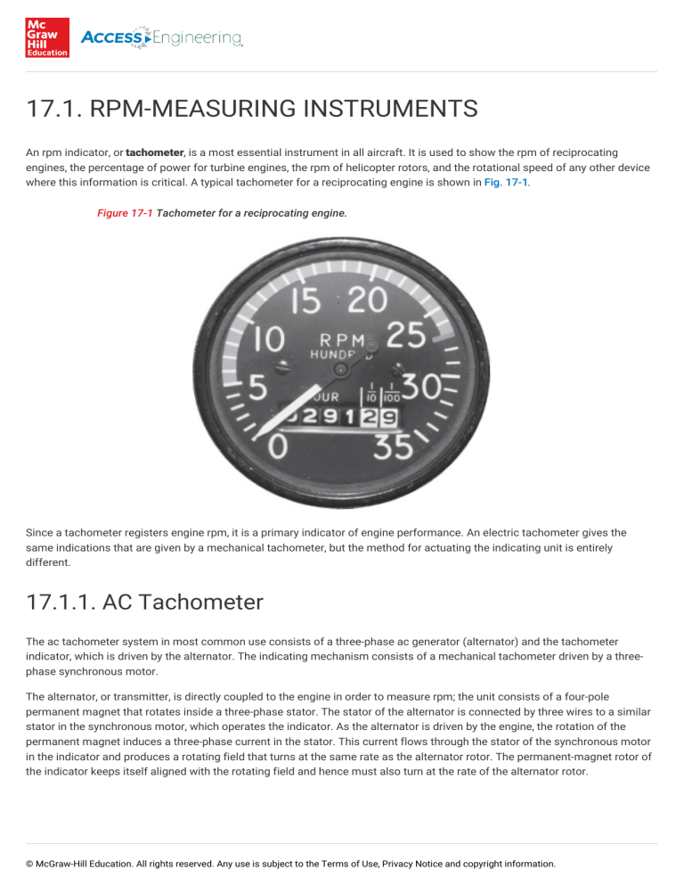
17.1. RPM-MEASURING INSTRUMENTS An rpm indicator, or tachometer, is a most essential instrument in all aircraft. It is used to show the rpm of reciprocating engines, the percentage of power for turbine engines, the rpm of helicopter rotors, and the rotational speed of any other device where this information is critical. A typical tachometer for a reciprocating engine is shown in Fig. 17-1. Figure 17-1 Tachometer for a reciprocating engine. Since a tachometer registers engine rpm, it is a primary indicator of engine performance. An electric tachometer gives the same indications that are given by a mechanical tachometer, but the method for actuating the indicating unit is entirely different. 17.1.1. AC Tachometer The ac tachometer system in most common use consists of a three-phase ac generator (alternator) and the tachometer indicator, which is driven by the alternator. The indicating mechanism consists of a mechanical tachometer driven by a threephase synchronous motor. The alternator, or transmitter, is directly coupled to the engine in order to measure rpm; the unit consists of a four-pole permanent magnet that rotates inside a three-phase stator. The stator of the alternator is connected by three wires to a similar stator in the synchronous motor, which operates the indicator. As the alternator is driven by the engine, the rotation of the permanent magnet induces a three-phase current in the stator. This current flows through the stator of the synchronous motor in the indicator and produces a rotating field that turns at the same rate as the alternator rotor. The permanent-magnet rotor of the indicator keeps itself aligned with the rotating field and hence must also turn at the rate of the alternator rotor. © McGraw-Hill Education. All rights reserved. Any use is subject to the Terms of Use, Privacy Notice and copyright information. The synchronous motor in the indicator is directly coupled to a cylindrical permanent magnet that rotates inside a drag cup, as shown in Fig. 17-2. As this magnet turns, it causes magnetic lines of force to drag through the metal cup and induce eddy currents in the metal. These eddy currents produce magnetic fields that oppose the field of the rotating magnet. The result is that as the speed of the rotating magnet increases, the drag or torque on the drag cup increases. The torque on the drag cup causes it to rotate against the force of the balancing hairspring and turn the pointer on the indicating dial. The distance through which the drag cup rotates is proportional to the speed of the synchronous motor; hence it is also proportional to the engine speed. Figure 17-2 Three-phase tachometer system. Modern electronic tachometers may use a frequency counter circuit to determine engine rpm as shown in Fig. 17-3. The rpm sensor in this circuit is a single-phase ac generator which produces a variable frequency ac output. The frequency is a function of engine rpm; the faster the engine turns, the higher the frequency. The variable frequency alternating current is sent to a frequency counter circuit that literally "counts" each ac pulse and converts the information into a digital signal. The digitized rpm data is then sent to an electronic display processor or directly to the display itself. In this system there is no dedicated rpm gauge; the information can be shown as a traditional "round dial" of digital format on a multifunction display. There are also some modern tachometer sensors which connect to the magneto of a piston engine and send an output signal to an engine control processor. The output of the processor is used to create the rpm display on an LCD instrument panel. Figure 17-3 A frequency counter tachometer. © McGraw-Hill Education. All rights reserved. Any use is subject to the Terms of Use, Privacy Notice and copyright information.
