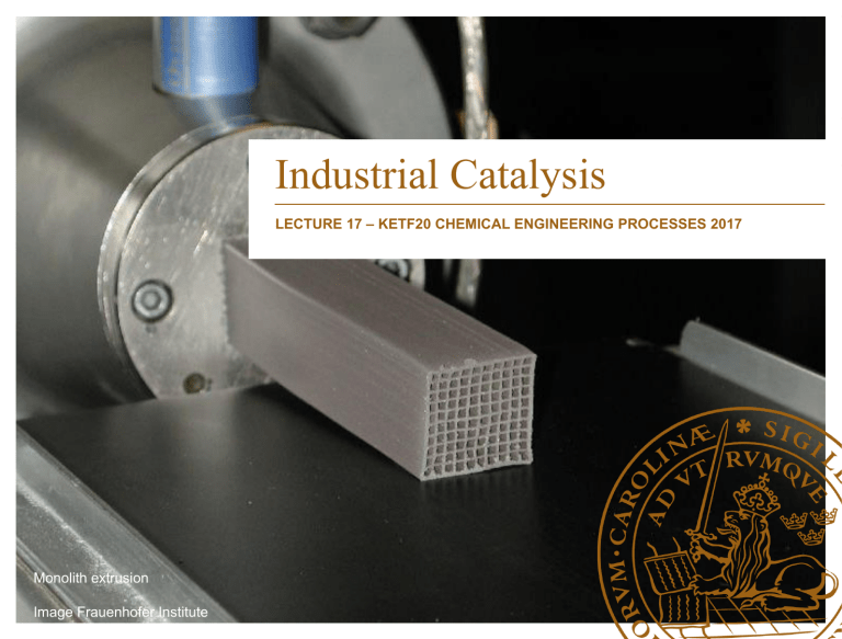
Industrial Catalysis LECTURE 17 – KETF20 CHEMICAL ENGINEERING PROCESSES 2017 Monolith extrusion Image Frauenhofer Institute Outline • Introduction and recap • Catalyst synthesis • Reactor loading • Catalyst activation • Catalyst deactivation 2 Introduction and recap • Structure – An industrial catalyst consists of three (3) parts • Carrier • Support • Active phase – Each with its own purpose 3 Introduction and recap • Carrier – Provides structure to the reactor bed – Determines of heat and mass transfer – Determines bed pressure drop – Ceramic or metallic – Should be resistant to mechanical stress 4 Introduction and recap Different catalyst carriers. 5 Introduction and recap • Support – Provides surface area for reaction – May be the material of the carrier – Common materials • Alumina • Silica • Ceria • Mixed oxides • Active carbon 6 Introduction and recap • Active phase – Contain sites where reaction occur – Metals or metal oxides – Metals from transition metal group in periodic table • Pt • Pd • Cu • Co • Ni • Rh 7 Introduction and recap The different elements to heterogeneous catalysis Image from Rothenberg Catalysis concepts and green applications 8 Catalyst manufacturing • Catalyst manufacturing – black magic revealed • Involves many different steps – Support preparation – Active phase preparation – Post-treatment – Forming – Activation 9 Catalyst manufacturing • Two main classes of catalysts • Bulk catalysts – Ammonia synthesis – Hydrocracking – Zeolites • Impregnated catalysts – Precious metal based 10 Catalyst manufacturing Bulk catalysts Impregnated Impregnated catalysts catalysts Precipitation (Silica/ Alumina) Wet impregnation (Automotive) Hydrothermal synthesis (Zeolites) Incipient wetness (Pt/Sn/Al2O3) Fusion/alloy leaching (Mixed oxides) Ion exchange (Acidic zeolite) 11 Catalyst manufacturing • Precipitation • Used for preparing – The bulk catalyst – The support material of impregnated catalysts • Mixing of metal salts in water • Adding reagent to shift pH 12 Catalyst manufacturing Precipitation of carbonate salt 13 Catalyst manufacturing Properties of aged precipitate Images Hans T. Karlsson 14 Catalyst manufacturing • Example – Synthesizing NiAl2O4 for pre-reforming of higher hydrocarbons – Mix nitrate salts of Ni and Al in deionized water – Use a ratio of 2:1 (Al:Ni) – Heat solution to 60 C – Add ammonium carbonate 15 Catalyst manufacturing • Example – Observe precipitation – Age precipitate for 4h at 60 C – Filter precipitate – Wash filter cake with deionized water – Dry at 120 C for 4 h – Calcine dry precipitate at 1,200 C – Verify phase by PXRD – Then continue with pellet formation 16 Catalyst manufacturing • Hydrothermal synthesis – Heating of precipitate, gel or flocculate – In aqueous solvent – 100-300 C – Changes in particles with respect to • Texture • Structure • Crystal • Particle size 17 Catalyst manufacturing Hydrothermal synthesis Image from Rothenberg Catalysis concepts and green applications 18 Catalyst manufacturing • Fusion/alloy leaching – Starting with a metal material – Melting – Casting into ingots – Cooling/annealing – Crushing 19 Catalyst manufacturing • Fusion/alloy leaching – Screening (size sorting) – Activation by leaching with caustic or acidic solution – Raney nickel example • NiAl alloy • Al removed by leaching (70-100 C) • Sponge Ni active catalyst • Low cost alternative to PGM in saturating benzene 20 Catalyst manufacturing • Wet impregnation – Wetting entire catalyst with dissolved precursor – Allowing precursor to adsorb onto catalyst – Drying after allowing enough time for adsorption – Determined by Darcy’s law 21 Catalyst manufacturing Difference between wet impregnation (a) and dry impregnation (b) Image from de Jong 2009 Impregnation possibilities Image from de Jong 2009 22 Catalyst manufacturing • Wet impregnation – Low precursor concentration - precursor-support interaction dominating – High precursor concentration - the species interacting with support form seeds for crystallization upon drying – Repeated many times (10) – Two types of interactions • Electrostatic interactions • Grafting through ligand substitution – Examples 3-way catalysts 23 Catalyst manufacturing Electrostatic interactions(a) Grafting via ligand exchange (b) Image from de Jong 2009 24 Catalyst manufacturing • Incipient wetness – Measure the pore volume of the catalyst – Decide the concentration of active phase – Prepare a mixture with the right concentration – Add enough liquid to fill the pore system – Catalyst is still dry to the touch – Example CuMnO/Al2O3 for VOC abatement 25 Catalyst manufacturing • Ion exchange – Used for changing cation (e.g. zeolites) – Treating material with solution with desired cation – Ion exchange between H+ and desired cation – Can be mordenite substituted with Ce4+ – Improved selectivity for N2O decomposition 26 Catalyst manufacturing • Summary – Two main ways of preparing catalyst • Bulk catalysts • Impregnated catalysts – Precipitation key step in forming the carrier/bulk catalyst – Active phase added in solution • Wet impregnation • Incipient wetness 27 Catalyst manufacturing • Unit operations of catalyst manufacture – Support preparation – Active phase preparation on support – Post treatment – Forming – Activation – Storage 28 Precipitation Support preparation Gelation Active phase preparation Impregnation Ion exchange Filtration Drying Post-treatment Calcination Extrusion Forming Pelleting Activation Unit operations of catalyst manufacturing 29 Catalyst manufacturing • Unit operations of catalyst manufacture – Support preparation is usually produced via precipitation or gelation – Active phase added by impregnation – Post treatment (washing, filtration, drying, calcination) – Forming (pellet, monolith) – Activation (reduction) – Storage 30 Catalyst manufacturing • Calcination – High temperature process – Inducing reaction of precursor • Decomposition of nitrate • Decomposition of acetate • Removal of chlorine – Assuring right crystal formation – Atmosphere influence end-result 31 Catalyst manufacturing Air gives more closed pore system Air yields larger crystalites of Ni J. Catal 260 (2008) 227 J. Catal 260 (2008) 227 32 Catalyst manufacturing A typical calcination schedule for noble metal catalysts on alumina 33 Catalyst manufacturing • Forming – Dry pressing (pelletization of powder) – Wet forming (making paste out of powder) – Adding binders and additives – May require second calcination step 34 Catalyst manufacturing • Forming – Required for nonfluidized catalysts – Pre-densification required (kneading) – Can be accomplished in washing/ion exchange – Combined with addition of tableting aids or binders 35 Catalyst manufacturing • Forming – Tableting – Extrusion – Granulation (spherudizing) • Inevitable lower activity compared to powder • Introduces – Diffusion limitations – Aids for forming (graphite, silicates, MgOH/MgO) 36 Catalyst manufacturing • For tableting the densified powder is dried and pulverized • Powder is screened – 6 mesh if 12-18 mm (1/2” to 3/4”) – 10 or 12 mesh if 6-10 mm (1/4” to 3/8”) • Pilling aid may also be introduced at this stage • May require post-calcination 37 Catalyst manufacturing 38 Catalyst manufacturing • Extrusion combined with densification • Moist clay of catalyst powder + water + binder • Pushed through a die to form catalyst – Round – Trilobe – Quatrolobe – Other shapes • Limits in size 20 mm in diameter • Expansion after die • Dried, calcined, post-treated 40 Catalyst manufacturing 41 Catalyst manufacturing 42 Catalyst manufacturing • Granulation – Spraying slurry on tilted disk/pan – Disk rotates and spheres build up – Large particles are concentrated to top layer – Falls out of pan at different size depending on tilt angle – Less uniform than tabletting – Requires post treatment 43 Catalyst manufacturing Catalyst manufacturing • Activation – Is performed on what is sometimes called a precatalyst – Oxidation – Reduction – Be carful to avoid pyroforic situations (CuZnO/Al2O3) – Initial and after deactivation (re-activation) 45 Catalyst manufacturing • Industrial example of number of steps 1. Dissolve salts in water 2. Change pH to induce precipitation 3. Wait for secondary precipitation (aging) 4. Wash by deionized water 5. Filter 6. Wash filter cake 46 Catalyst manufacturing • Industrial example of number of steps 7. Drying 8. Calcining 9. Reslurry in water (e.g. for ion exchange) 10. Filter 11. Wash 12. Dry 47 Catalyst manufacturing • Industrial example of number of steps 13. Add solution of promoter and/or binder 14. Form paste via kneading 15. Extrude 16. Dry 17. Granulate 18. Mix with prilling lubricant or binder 48 Catalyst manufacturing • Industrial example of number of steps 19. Prill 20. Calcine 21. Add active phase via impregnation 22. Calcine 23. Activate 24. Stabilize (inert environment etc.) 25. Store or use 49 Catalyst manufacturing • Summary – Several unit operations involved in catalyst synthesis – Industrial schemes quite complicated – Much washing of material – Allowing for removal of catalyst poisons from manufacture (Cl-) – Generating quite a lot of wastewater 50 Reactor loading • Important aspect of catalytic reactor design • Ensure similar bed properties every time – Heat transfer – Pressure drop – Temperature gradient • Industrial scale 51 Reactor loading 52 Reactor loading 53 Reactor loading 54 Reactor loading • Important to ensure correct packing of catalyst bed • Make sure that catalyst mass fill entire reactor • Evenly distributed and packed in the reactor • Take care to have guard beds in place and exchange material with set interval • Make sure layering is correct • Make sure the right dilution is used at the right position in the reactor 55 Reactor loading Catalyst bed with three concentrations of catalyst, e.g. Formox 56 Reactor loading • Hot spot is to be avoided • Using dilution of catalyst with inert • Use catalyst with less active phase • May contribute significantly to process economy and operability 57 Catalyst deactivation • Deactivation may have several causes • Such as: – Over-temperature – Changes in inlet composition – Process hygiene • Concerns the deactivation that occur after the first initial lowering of activity • After 50 -100 h and onwards 58 Catalyst deactivation 59 Catalyst deactivation • Poisoning – Interaction with the active phase – Usually with an electronegative specie • Sulphur • Chlorine • Arsenic • Phosphorous • But also other compounds (e.g. CO, O2, NH3) 60 Catalyst deactivation Most active phases Most catalyst poisons 61 Catalyst deactivation • Poisoning – Selective towards the active phase – One molecule may influence more than one active site – Electronic effects spill over to adjacent sites – Competitive adsorption with reactants – Reversible or irreversible 62 Catalyst deactivation Example of catalyst poisoning of fuel cell catalyst Image from Osakagas.co.jp 63 Catalyst deactivation • Sulphur poisoning major problem in fuel processing • Two mechanisms – Surface coverage – Formation of bulk sulphur • The first process is reversible • The second is irreversible 64 Catalyst deactivation Ni-catalyst deactivation via sulphur addition Image from Chrisgas special issue 65 Catalyst deactivation • Clearly see two effects • Initial lowering of activity due to surface adsorption • Long term lowering of activity due to bulk sulphuide formation • Can be counteracted by higher temperatures • Lower the stability of the surface sulphides • Lower formation rate of bulk sulfide 66 Catalyst deactivation • Fouling – Covering of the active part of a catalyst – Physical blocking of active sites – Physical blocking of pores – Renders part of the catalyst useless – Can be formed or introduced • Coke formation • Ash coverage 67 Catalyst deactivation • Three reactions to consider: 2 CO C(s) + CO2 (exothermal) CH4 C(s) + 2 H2 (endothermal) CnHm polymers Coke + x H2 (endothermal, ir) • Coke formation depends on the catalyst kinetics and operation conditions • Dent carbon appears at lower temperature in higher amounts than predicted by equilibrium 68 Catalyst deactivation • Intrinsic property for coking in feedstock: ethylene >> benzene, toluene > nheptane > n-hexane > cyclohexane > trimethyl-butane ~ n-butane ~ carbon monoxide > methane • Inlet conditions important Test rig for evaluating steam reforming and pre-reforming catalysts 69 Catalyst deactivation Coke formed on steam reforming catalysts 70 Catalyst deactivation • Prevention of coking in steam reforming − Addition of alkali (not necessary for natural gas) − Addition of PGM to Ni-phase − Choice of carrier material − Use of PGM catalyst − Sufficient S:C ratio − Inlet conditions controlled − Product recycle • Can be recovered in part by combined heat and steam treatment 71 Catalyst deactivation • Ash coverage – Different from coking – Not formed in reactor – Introduced via gas stream – Fouling and chemical transfer 72 Catalyst deactivation 10 Fresh catalyst K2SO4 Exposed catalyst Conversion (%) 8 6 4 2 600 620 640 660 680 Temperature (C) Results from exposure of salt aerosols on steam reforming catalysts From Hydrogen an energy carrier of the future 73 700 720 Catalyst deactivation • Ash fouling – Presence of ash covers active phase – Multiple effects • Physical coverage • Chemical interactions – Lowers performance drastically 74 Catalyst deactivation • Sintering – Two types • Active phase • Support – Results in loss of metal surface directly or indirectly 75 Catalyst deactivation • Sintering – Oftentimes due to high temperatures • Increased to maintain activity • Excursions due to process upsets – Can be rapid if excess temperatures are reached – Initial deactivation often due to sintering phenomena – Example(Catal. Today 214 (2013) 12) • Pt catalysts for Fischer-Tropsch • Initial metal dispersion 89% • Reduced to 10% 76 Catalyst deactivation • Sintering – Example initial deactivation – From Regale et al. Catal. Today 214 (2013) 12 • Pt catalysts for Fischer-Tropsch • Initial metal dispersion 89% • Reduced to 10% after 12 h on-stream • Particle size increased from 3.7 nm to 10.9 nm 77 Catalyst deactivation • Sintering of active phase • Two mechanisms – Atomic migration (THüttig=0.3 * Tmelt) – Crystallite migration (TTamman=0.5 * Tmelt) 78 Catalyst deactivation • Deactivation – Important factor in catalyst design – Avoid if possible • Process hygiene • Process control – Design around if not • Guard bed • Egg yolk catalyst Egg yolk catalyst – Essential to include in modelling 79 Concluding remarks • Deactivation key to catalyst performance – Poisoning – Fouling – Sintering • Process hygiene and control essential • Need to be taken into account in designing and modelling • Will occur but deactivation rate should be minimized/optimized 80 Concluding remarks • Precipitation key step to catalyst synthesis • Active phase added by impregnation • Industrial schemes quite complicated • Waste management should be taken into account • Reactor loading important factor for repeatability • Large scale industrially 81


