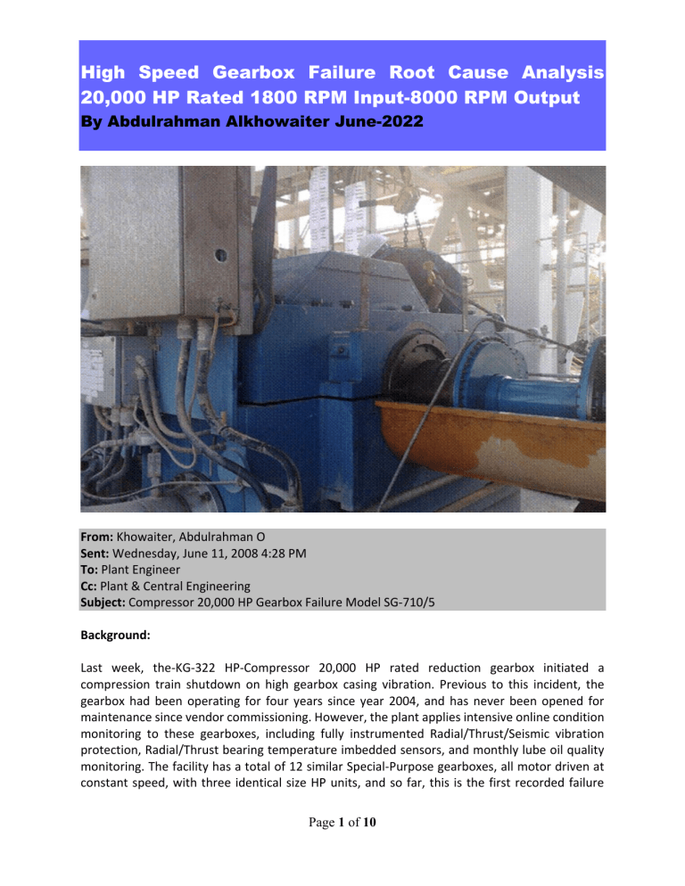
High Speed Gearbox Failure Root Cause Analysis 20,000 HP Rated 1800 RPM Input-8000 RPM Output By Abdulrahman Alkhowaiter June-2022 From: Khowaiter, Abdulrahman O Sent: Wednesday, June 11, 2008 4:28 PM To: Plant Engineer Cc: Plant & Central Engineering Subject: Compressor 20,000 HP Gearbox Failure Model SG-710/5 Background: Last week, the-KG-322 HP-Compressor 20,000 HP rated reduction gearbox initiated a compression train shutdown on high gearbox casing vibration. Previous to this incident, the gearbox had been operating for four years since year 2004, and has never been opened for maintenance since vendor commissioning. However, the plant applies intensive online condition monitoring to these gearboxes, including fully instrumented Radial/Thrust/Seismic vibration protection, Radial/Thrust bearing temperature imbedded sensors, and monthly lube oil quality monitoring. The facility has a total of 12 similar Special-Purpose gearboxes, all motor driven at constant speed, with three identical size HP units, and so far, this is the first recorded failure Page 1 of 10 High Speed Gearbox Failure Root Cause Analysis 20,000 HP Rated 1800 RPM Input-8000 RPM Output By Abdulrahman Alkhowaiter June-2022 incident on any of the 12 gearboxes. The gearboxes were packaged by the compressor manufacturer for their compressor skids and all gearboxes were manufactured in Europe. From a process parameter point of view, this gearbox has not been exposed to any unusual operating load conditions for the past four years, such as: over-speed (constant speed motor driven), excess driver torque motor torque data was given to Gearbox OEM during design in 2002, or excess driven machine torque, such as seizing of compressor in its casing. After the shutdown, the gearbox inspection hatch was opened, and interior damage to the bull gear was noted. The remaining drive train such as compressor and motor driver were all found in good condition. The gearbox was removed from field and sent to the central shops division. The facility personnel have made a very good preventative maintenance step by inspecting the gearbox and discovering the internal faults, before major damage has occurred to this critical gearbox. Page 2 of 10 High Speed Gearbox Failure Root Cause Analysis 20,000 HP Rated 1800 RPM Input-8000 RPM Output By Abdulrahman Alkhowaiter June-2022 Failure Analysis: The Gosp-1 HP compressor gearbox at central shops was opened yesterday for analysis of failure. As can be seen from the photos, the Bull gear has moved axially from its design position by a distance of approximately 12 cm. This led to rubbing of the bull gear with the oil spray supports and radial bearing housing, and this produced vibration which caused a seismic vibration shutdown on Hi-Hi vibration. Examination of the gearbox upper and lower halves revealed that the gearbox is a steel fabrication of heavy duty construction, with high stiffness, and advanced design. All welds were of excellent quality, so the gearbox casing or footing were not contributing to this incident. All pictures above are the as-found condition, no cleaning has been applied. Both bull and pinion radial–thrust bearings and shaft journals were found to be in as-new condition. The following are critical points for the analysis: 1. All gearbox bearings were found in excellent condition, with no signs of internal rubbing, lack of lubrication, poor quality lubrication, or misalignment of wear pattern. There were no signs of varnishing on any of the radial-thrust bearings, which is also an indicator that they have not been exposed to excessive temperatures. If the gearbox was subjected to some unusual torque loads, a typical finding would be overheating and brown varnish stains on the HS radial bearings, however, no evidence was found. The fact that all radial bearings Babbitt surface were found with excellent surface condition is further proof that they were not exposed to vibration beyond the manufacturer design limits during the four years of operation. All gearbox historical vibration-temperature data is available with the facility. The shaft journals and thrust collars were found in excellent condition. 2. The gearbox low speed and high speed shaft coupling hubs were found to be in proper place, with no movement out of position, looseness, or mechanical damage. No significant indication of over-torque was found, and the same applies to the HS-LS flexible coupling spools. The coupling bolts are in good condition. 3. The bull gear rotor design is a two piece fabricated construction; forged bull gear, with center bored, to allow shrink-fitting to a large diameter, high stiffness low speed shaft. No keys are used for torque transmission, so by design, all shaft torque to bull gear is transmitted by the frictional shrink interference fit only. The low speed shaft diameter is high, giving a large cylindrical surface area to achieve a sufficient shrink fit. However, the actual shrink fit used on this gearbox during factory assembly was at first unknown until the gear was disassembled in the shop. There is always a possible difference between design shrink fit, and the actual shrink fit at assembly due to the possibility of human error. OEM stated in a recent letter that the design shrink interference fit of the shaft to the wheel bore is 0.379mm minimum, and maximum interference fit of 0.44 mm diametral. The LS Shaft Diameter (nominal) is 360.44 Page 3 of 10 High Speed Gearbox Failure Root Cause Analysis 20,000 HP Rated 1800 RPM Input-8000 RPM Output By Abdulrahman Alkhowaiter June-2022 mm. By changing to imperial units, the OEM design shrink fit is 0.015 to 0.0175 inch on the 14.2 inch OD shaft, which means that the design interference fit range is from 0.001 to 0.0012 inch, per inch diameter. The actual as found interference once disassembled, was only 0.008 inches diametral, far below OEM standards. 4. The bull gear teeth in general, except for the last 2cm flank that were exposed to edge rubbing, are in good condition. The pinion teeth are not severely damaged, but there is a tooth face wear pattern most likely resulting from the short period when the primary failure mode of bull gear movement occurred, and the continuous rubbing of bull gear caused a wobbling and a modulating teeth pattern since they have operated for hours at this condition, under load. However, please note that the pinion teeth unusual surface pattern is a secondary damage, and not primary. 5. At initial impressions, it was suspected that some type of over torque situation led to the bull gear rotating on the LS shaft, and overpowering the shrink fit. However, the pictorial evidence attached above from the opened gearbox, shows that the bull gear did not rotate on the shaft for the first 12 cm of axial displacement. This means that an over torque scenario never occurred as a primary failure mode, or the shaft underneath the bull gear would have been heavily scored and damaged from the resistance to over torque. All evidence points to loss of bull gear to LS shaft shrink fit during normal operation, and gradual axial slipping toward the opposite bearing, until rubbing contact occurred and heavy vibration resulted. This slipping is assisted by the normal axial force acting on single helical gears. We have never opened this gearbox before, and no overspeed incidents are possible due to constant speed driver, and no evidence of external over torque to gearbox was found, then the only possible root causes of failure are: Insufficient shrink fit by design, or insufficient shrink fit during assembly, or relaxation of initial shrink fit due to bull gear forging heat treatment process errors. There is no physical evidence of severe overheating of the gearbox during operation which would lead to any bull gear unusual thermal growth and looseness. The only sign of overheating in the pictures above are the secondary damage after the bull gear sidewall rubbed other parts during operation. Conclusions: From the evidence observed, the root cause of gearbox failure is attributed to loss of bull gear shrink fit as a result of insufficient design interference fit or factory assembly errors such as incorrect bore/shaft machining dimensions. In general, we consider the present gearbox design shrink fit limits of only 0.001 to 0.0012 inch/inch diameter, to have borderline safety factor to overcome the effects of differential thermal expansion between shaft and gear, combined with Page 4 of 10 High Speed Gearbox Failure Root Cause Analysis 20,000 HP Rated 1800 RPM Input-8000 RPM Output By Abdulrahman Alkhowaiter June-2022 the reduction in shrink fit due to expansion of bore under centrifugal stresses at normal operating speeds. However, since the shaft to gear holding power is in conflict with total tensile stress in gearbox which arises from centrifugal forces and tooth stress, it is possible that OEM limited shrink fit to 0.0012 inch/inch diameter to reduce overall stresses on gear. The primary root cause is the as found manufacturing defect of having only 0.008-inch interference total which led to a primary failure mode of axial displacement of the bull gear (not LS shaft). Overall, the gearbox is of high quality, heavy duty construction, as is evident by its condition now after the failure. All major mechanical parts such as bearings were so heavily designed that they show no wear or tear under the failure conditions. Therefore, we consider this error something that can be rectified and permanently solved. We have the capability to perform an engineering analysis of the Bull Gear operating stresses and conditions, and applying a shrink fit that will resist all possible normal operating stresses, without overstressing the yield strength of the bull gear forging material. However, we recommend at this stage, to leave all parts in the as-found condition, allow OEM to complete their investigation, and propose improved shrink fitting design parameters to this gearbox LS rotor. Recommendations: 1. Install a new gear set into this gearbox, as these gearboxes are normally purchased with spare gear sets. Insure that shrink fit is measured at shops and increased to new dimensional settings to be agreed upon with OEM and myself. 2. Inspect all remaining 11 gearboxes, using the inspection hatch, for any visible signs of bull gear displacement, within 1-month maximum from receipt of this failure report. Remove any gearbox found with bull gear displacement, to Central Shops, without delay. 3. Inspect and calibrate all gearbox seismic transducers, as these transducers are responsible for protection from similar failures. This can be done on-line, by isolating the transducer, and applying a shaker to test output to monitors. This should be done within two weeks’ time period. 4. Issue written letter to both plants operation personnel, warning that no compression train shall be restarted if the train was shut down by the gearbox seismic or displacement transducers. 5. Arrange scheduled gearbox overhauls at Central Shops for all remaining 11 gearboxes, to measure and upgrade the bull gear shrink fits. Page 5 of 10 High Speed Gearbox Failure Root Cause Analysis 20,000 HP Rated 1800 RPM Input-8000 RPM Output By Abdulrahman Alkhowaiter June-2022 Page 6 of 10 High Speed Gearbox Failure Root Cause Analysis 20,000 HP Rated 1800 RPM Input-8000 RPM Output By Abdulrahman Alkhowaiter June-2022 Page 7 of 10 High Speed Gearbox Failure Root Cause Analysis 20,000 HP Rated 1800 RPM Input-8000 RPM Output By Abdulrahman Alkhowaiter June-2022 Page 8 of 10 High Speed Gearbox Failure Root Cause Analysis 20,000 HP Rated 1800 RPM Input-8000 RPM Output By Abdulrahman Alkhowaiter June-2022 Page 9 of 10 High Speed Gearbox Failure Root Cause Analysis 20,000 HP Rated 1800 RPM Input-8000 RPM Output By Abdulrahman Alkhowaiter June-2022 Page 10 of 10
