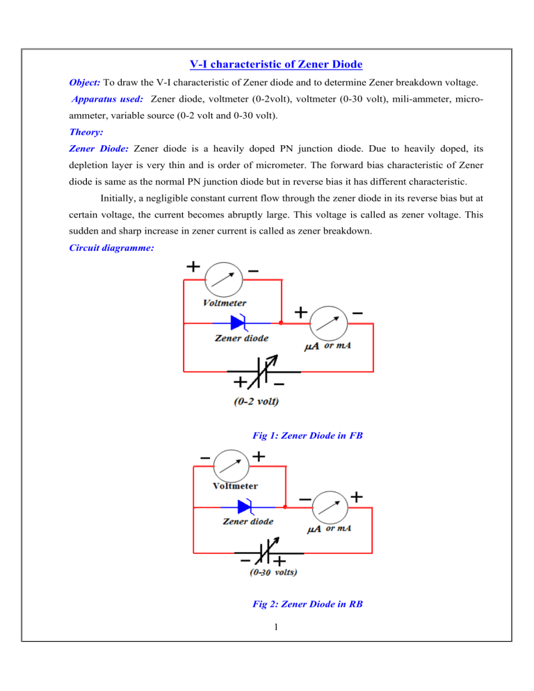
V-I characteristic of Zener Diode Object: To draw the V-I characteristic of Zener diode and to determine Zener breakdown voltage. Apparatus used: Zener diode, voltmeter (0-2volt), voltmeter (0-30 volt), mili-ammeter, microammeter, variable source (0-2 volt and 0-30 volt). Theory: Zener Diode: Zener diode is a heavily doped PN junction diode. Due to heavily doped, its depletion layer is very thin and is order of micrometer. The forward bias characteristic of Zener diode is same as the normal PN junction diode but in reverse bias it has different characteristic. Initially, a negligible constant current flow through the zener diode in its reverse bias but at certain voltage, the current becomes abruptly large. This voltage is called as zener voltage. This sudden and sharp increase in zener current is called as zener breakdown. Circuit diagramme: Fig 1: Zener Diode in FB Fig 2: Zener Diode in RB 1 Observation: 1. Least count of voltmeter (0-2volt) =0.02 volt 2. Least count of voltmeter (0-30volt) =0.5 volt 3. Least count of miliammeter =0.2 mA 4. Least count of micro-ammeter =5 μA 5. VF and IF for PN junction Diode in FB 6. VR and IR for PN junction diode in RB Sr. VF IF No. (Volt) (mA) 1. 0 0 Sr. VR IR No. (Volt) (mA) 2. 0.1 0 1. 0 0 3. 0.2 0 2. 1 0 4. 0.3 0 3. 2 0 5. 0.4 0 4. 3 0 6. 0.5 0 5. 4 0 7. 0.6 0.2 6. 5 0 8. 0.62 0.2 7. 6 0 9. 0.64 0.4 8. 7 0 10. 0.66 0.6 9. 8 0 10. 0.68 0.8 10. 8.8 0.2 11. 0.70 1.2 10. 9 0.4 12. 0.72 2.2 11. 9.2 3.0 13. 0.74 3.2 14. 0.76 5.2 15. 0.78 7.0 16. 0.80 9.4 Result: The V-I characteristic of Zener diode indicates that characteristic of Zener diode in forward bias is same as PN junction diode. In reverse bias, a negligible constant current flow through the zener diode but the current becomes abruptly large at certain voltage. This voltage is called as zener voltage. This sudden and sharp increase in zener current is called as zener breakdown. Vknee=0.7 volt and VZ= 9 volt. Precautions: 1. The connection should be tight otherwise fluctuation in voltage and current will happen. 2. At the turning point of curve, more reading should be taken. 3. For the plot of Graph, current should be taken mA for both forward and reverse biased diode. 4. The reading should be in multiple of least count. 2 V-I Characteristic Curve for Zener Diode in FB 3 V-I Characteristic Curve for Zener Diode In RB 4

