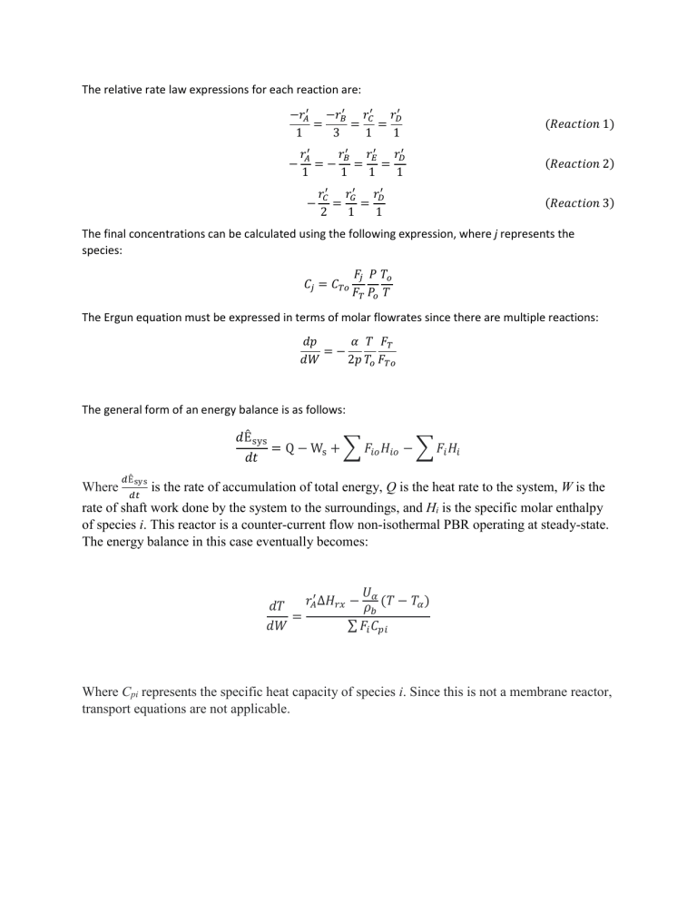
The relative rate law expressions for each reaction are: −𝑟𝐴′ −𝑟𝐵′ 𝑟𝐶′ 𝑟𝐷′ = = = 1 3 1 1 (𝑅𝑒𝑎𝑐𝑡𝑖𝑜𝑛 1) 𝑟𝐴′ 𝑟𝐵′ 𝑟𝐸′ 𝑟𝐷′ =− = = 1 1 1 1 (𝑅𝑒𝑎𝑐𝑡𝑖𝑜𝑛 2) 𝑟𝐶′ 𝑟𝐺′ 𝑟𝐷′ = = 2 1 1 (𝑅𝑒𝑎𝑐𝑡𝑖𝑜𝑛 3) − − The final concentrations can be calculated using the following expression, where j represents the species: 𝐶𝑗 = 𝐶𝑇𝑜 𝐹𝑗 𝑃 𝑇𝑜 𝐹𝑇 𝑃𝑜 𝑇 The Ergun equation must be expressed in terms of molar flowrates since there are multiple reactions: 𝑑𝑝 𝛼 𝑇 𝐹𝑇 =− 𝑑𝑊 2𝑝 𝑇𝑜 𝐹𝑇𝑜 The general form of an energy balance is as follows: 𝑑Êsys = Q − Ws + ∑ 𝐹𝑖𝑜 𝐻𝑖𝑜 − ∑ 𝐹𝑖 𝐻𝑖 𝑑𝑡 Where 𝑑Êsys 𝑑𝑡 is the rate of accumulation of total energy, Q is the heat rate to the system, W is the rate of shaft work done by the system to the surroundings, and Hi is the specific molar enthalpy of species i. This reactor is a counter-current flow non-isothermal PBR operating at steady-state. The energy balance in this case eventually becomes: 𝑈 𝑟𝐴′ ∆𝐻𝑟𝑥 − 𝜌𝛼 (𝑇 − 𝑇𝛼 ) 𝑑𝑇 𝑏 = ∑ 𝐹𝑖 𝐶𝑝𝑖 𝑑𝑊 Where Cpi represents the specific heat capacity of species i. Since this is not a membrane reactor, transport equations are not applicable.
