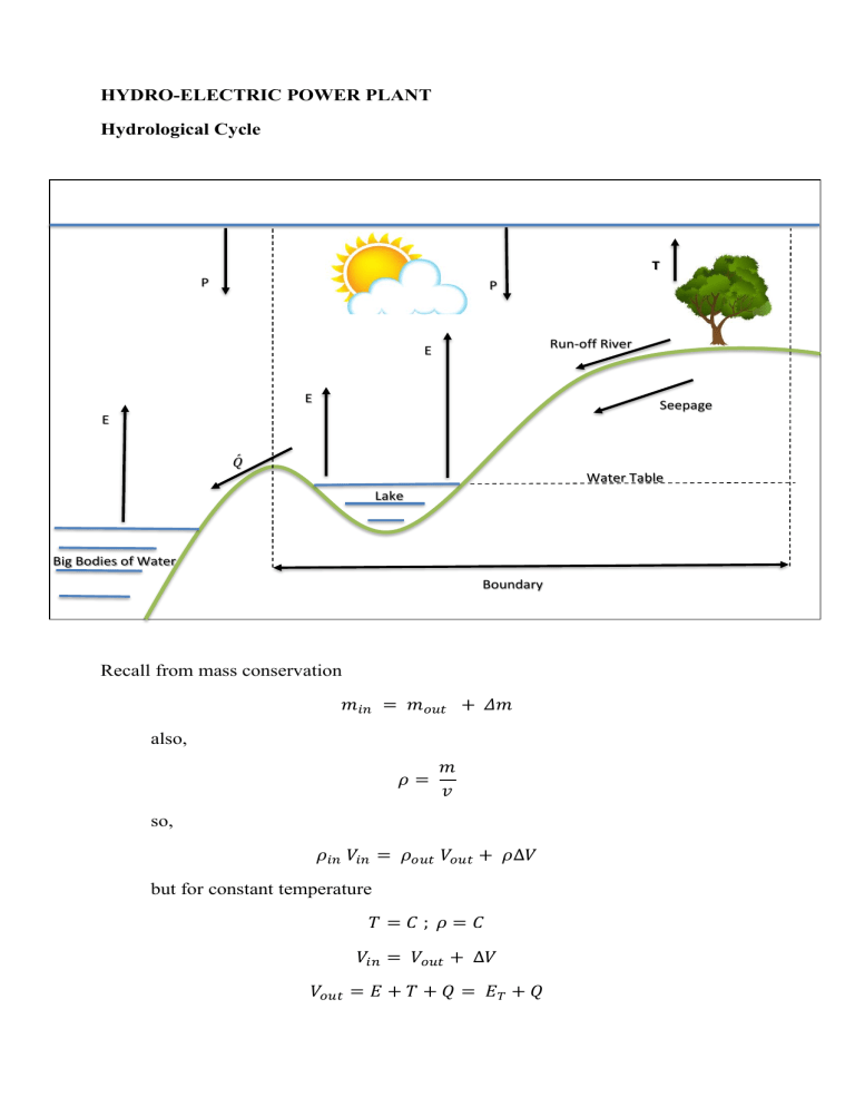
HYDRO-ELECTRIC POWER PLANT Hydrological Cycle T P P Run-off River E E Seepage E 𝑄ሖ Water Table Lake Boundary Big Bodies of Water Boundary Recall from mass conservation 𝑚𝑖𝑛 = 𝑚𝑜𝑢𝑡 + 𝛥𝑚 also, 𝜌= 𝑚 𝑣 so, 𝜌𝑖𝑛 𝑉𝑖𝑛 = 𝜌𝑜𝑢𝑡 𝑉𝑜𝑢𝑡 + 𝜌∆𝑉 but for constant temperature 𝑇=𝐶; 𝜌=𝐶 𝑉𝑖𝑛 = 𝑉𝑜𝑢𝑡 + ∆𝑉 𝑉𝑜𝑢𝑡 = 𝐸 + 𝑇 + 𝑄 = 𝐸𝑇 + 𝑄 Considering the Boundary 𝑃𝑇 - total precipitation 𝑃𝑇 = [𝐴𝑐 ] [ℎ𝑅 ] where: 𝐴𝑐 - catchment area or drainage area ℎ𝑅 - average rainfall and, 𝑄 𝑄ሖ = 𝑡 where: 𝑄ሖ - volume flowrate/discharge rate 𝑄 - total volume usually, 𝐸𝑇 = (%)𝑃𝑇 where: 𝐸𝑇 - total evaporation and transpiration ∆𝑆𝑤 = [𝐴𝑠 ][ℎ𝑠 ] where: ∆ℎ𝑠 - change in storage level Water power, Pw For pumps 𝑃𝑤 = 𝑄ሖ 𝛿𝑤 (𝑇𝐷𝐻) For turbines 𝑃𝑤 = 𝑄ሖ 𝛿𝑤 (𝐻) then, 𝑎𝑣𝑎𝑖𝑙. 𝑃𝑤 = 𝑄ሖ 𝛿𝑤 (𝐻𝑛𝑒𝑡 ) 𝑛𝑒𝑡 𝑃𝑤 = 𝑄ሖ 𝛿𝑤 (𝐻𝑎𝑣𝑎𝑖𝑙 ) avail. Pw → net Pw 𝐻𝑛𝑒𝑡 → 𝐻𝑎𝑣𝑎𝑖𝑙 𝑇𝑜𝑡𝑎𝑙 𝑃𝑤 = 𝑄ሖ𝛿𝑤 (𝐻𝑔 ) Total Pw → gross Pw 𝐻𝑔 → 𝑇𝑜𝑡𝑎𝑙 𝐻 → 𝑔𝑟𝑜𝑠𝑠 ℎ𝑒𝑎𝑑 𝐸𝑓𝑓. 𝑃𝑤 = 𝑄ሖ𝛿𝑤 (𝐻𝐸𝐹𝐹 ) 𝐸𝑓𝑓. 𝑃𝑤 → 𝑃𝑤 𝑖𝑛𝑙𝑒𝑡 𝑡𝑜 𝑡ℎ𝑒 𝑡𝑢𝑟𝑏𝑖𝑛𝑒 𝐻𝐸𝐹𝐹 → 𝐻 𝑢𝑡𝑖𝑙𝑖𝑧𝑒𝑑 𝑏𝑦 𝑡ℎ𝑒 𝑡𝑢𝑟𝑏𝑖𝑛𝑒 Impulse Turbine • Pelton wheel (high head) 𝐻𝑛𝑒𝑡 𝐻𝑔 z Reaction Turbine • Francis (medium head) • Kaplan (low head) HWE Hnet = Hg Surge Tank Generator Turbine z Draft Tube Tailrace TWE HEAD CALCULATION Hg Hnet Heffective Impulse ➢ Pelton wheel (high head) HWE-TWE Hg - z Hnet -hf Reaction ➢ Francis (medium head) ➢ Kaplan (low head) HWE-TWE Hg Hnet -hf where: HWE - head water elevation TWE - tailwater elevation z - turbine setting ℎ𝑣𝑒 - velocity head at exit ℎ𝑣𝑒 = 𝑣𝑒 2 2𝑔 ℎ𝐹 - friction head loss in the penstock in rpm Typical values of specific speed for the three types of runners Potter, P. J. (1988). Power plant theory and design. Malabar, FL: Krieger. Hydraulic Efficiency, 𝜂𝐻 𝜂𝐻 = 𝜂𝐻 = 𝜂𝐻 = 𝐻𝐸𝑓𝑓 𝐻𝑛𝑒𝑡 𝑥 100% 𝐸𝑓𝑓. 𝑃𝑤 𝑎𝑣𝑎𝑖𝑙 𝑃𝑤 𝑄ሖ𝛿𝑤 𝐻𝐸𝑓𝑓 𝑄ሖ𝛿𝑤 𝐻𝑛𝑒𝑡 𝑥 100% 𝑥 100% Volumetric efficiency, 𝜂𝑣 η𝑣 = 𝑄ሖ −𝑄𝐿 𝑄ሖ 𝑥 100% where: 𝑄𝐿 = Leakage Losses Mechanical efficiency, 𝜂𝒎 𝜂𝑚 = 𝐵𝑃 𝐼𝑃 𝑥 100% Overall turbine efficiency, 𝜂 𝑇 𝜂 𝑇 = 𝜂𝐻 𝑥 η𝑣 𝑥 𝜂𝑚 𝜂𝑇 = 𝐵𝑃 𝑎𝑣𝑎𝑖𝑙.𝑃𝑤 𝑥 100% Generator efficiency, 𝜂𝑔 𝜂𝑔 = 𝐸𝑃 𝐵𝑃 𝑥 100% Overall Hydraulic Plant efficiency, 𝜂𝑜 𝜂𝑜 = 𝜂 𝑇 𝑥 𝜂𝑔 𝜂𝑜 = 𝐸𝑃 𝑎𝑣𝑎𝑖𝑙.𝑃𝑤 𝑥 100% But if A.P (auxiliary power) is given 𝜂𝑜 = 𝐸𝑃 − 𝐴𝑃 𝑎𝑣𝑎𝑖𝑙.𝑃𝑤 𝑥 100% Overall hydraulic conversation efficiency, 𝜂𝑜𝑐 𝜂𝑜𝑐 = 𝐸𝑃 − 𝐴𝑃 𝑡ℎ𝑒𝑜 𝑃𝑤 𝑥 100% where: 𝑇ℎ𝑒𝑜. 𝑃𝑤 = 𝑄ሖ𝑡ℎ𝑒𝑜 𝛿𝑤 𝐻𝑔 Specific speed • for turbine 𝑁𝑠 = 𝑁√𝐵𝑃 5 𝐻4 : 𝑟𝑝𝑚 = 𝑠𝑝𝑒𝑒𝑑√𝐵𝑃/𝑟𝑢𝑛𝑛𝑒𝑟 𝑚 • for pumps 𝑁𝑠 = 𝑁√𝑄ሖ : 𝑟𝑝𝑚 = 3 𝐻4 𝑠𝑝𝑒𝑒𝑑 √𝑔𝑝𝑚 𝑚 Affinity Laws At D = C; H varies (𝑯𝑶 → 𝑯𝑵 ) 𝑸ሖ𝑵 𝑸ሖ𝑶 1 = 𝐻 2 [ 𝑁] 𝐻𝑂 1 ; 𝑁𝑁 𝑁𝑂 = 𝐻 2 [ 𝑁] 𝐻𝑂 3 ; 𝐵𝑃𝑁 𝐵𝑃𝑂 = 𝐻 2 [ 𝑁] 𝐻𝑂 At H = C; D varies (𝑫𝑶 → 𝑫𝑵 ) 𝑸ሖ𝑵 𝑸ሖ𝑶 𝐷 2 = [ 𝑁] ; 𝐷𝑂 𝑁𝑁 𝑁𝑂 = 𝐷𝑂 𝐷𝑁 ; At D, H, N = C; Q’ varies, (𝑸ሖ𝑶 → 𝑸ሖ𝑵 ) 𝐵𝑃𝑁 𝐵𝑃𝑂 = 𝑄𝑁 𝑄𝑂 𝐵𝑃𝑁 𝐵𝑃𝑂 𝐷 = [ 𝑁] 𝐷𝑂 2 Problems: 1. A lake having a surface area of 39 000 hectares receives its water as run-off and seepage from the drainage of an area 520 000 hectares including its own area. The lake empties through a single outlet. The lake level was 550 m at the beginning of a given month of 720 hours and 550.6 m at the end. The average rainfall over the area during the month was 10.2 cm. If 40% of the precipitation was evaporated and transpired, what was the average flow through the outlet in sec-m during the month? If the river forming the outlet of the lake has a rapid starting which descends 65 m within a short distance, what energy could have been developed ideally at this site for the month? 2. A factory is situated at a fall of 20 m drop in a river. The factory requires a source of energy with a capacity of 300 Hp all during the year. The river flow on the average in one year is as follows: 5.5 sec-m for 2 months, 2.75 sec-m for 2 months, 2.0 sec-m for 1 month, 1.0 sec-m for 7 months. a) If the site is developed as a run-off river plant without storage, what capacity must be provided in a standby plant? The efficiency of the hydraulic plant will be 80% over-all. b) If a reservoir could be developed upstream, what would be the percentage of the stored water that would provide margin for evaporation and seepage? Would a standby plant be necessary? 3. The difference between the headwater and the tail water elevation is 180 m. The head utilized by the turbine is 140 m when the flow is 2.3 cumex. The head loss at the penstock is 20 m and leakage loss 0.085 cumex. The frictional losses in the turbine are 75 kW. Calculate: a) 𝜂𝐻 b) η𝑣 c) power delivered to the shaft, d) turbine power, e) 𝜂𝑚 f) 𝜂 𝑇 4. A hydraulic turbine running at 1500 rpm at a head of 80 ft. has an efficiency of 87%. The flow is 60 sec-ft. a) Calculate the specific speed of the turbine b) What would be the corresponding changes in flow, speed and brake power if the turbine will operate at a head of 160 ft? c) If the runner diameter will be twice that of the original, what will be the new flow, speed and brake power? 5. Specify the type and the number of runners to be used by a hydraulic plant at a head of 80 ft. and having a discharge of 15 000 cfs which will be directly coupled to a 60 Hz, 90-pole generators.


