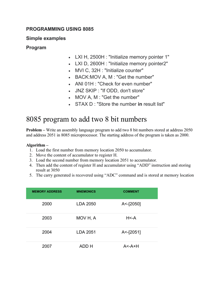
PROGRAMMING USING 8085 Simple examples Program • • • • • • • • LXI H, 2500H : "Initialize memory pointer 1" LXI D, 2600H : "Initialize memory pointer2" MVI C, 32H : "Initialize counter" BACK:MOV A, M : "Get the number" ANI 01H : "Check for even number" JNZ SKIP : "If ODD, don't store" MOV A, M : "Get the number" STAX D : "Store the number in result list" 8085 program to add two 8 bit numbers Problem – Write an assembly language program to add two 8 bit numbers stored at address 2050 and address 2051 in 8085 microprocessor. The starting address of the program is taken as 2000. Algorithm – 1. Load the first number from memory location 2050 to accumulator. 2. Move the content of accumulator to register H. 3. Load the second number from memory location 2051 to accumulator. 4. Then add the content of register H and accumulator using “ADD” instruction and storing result at 3050 5. The carry generated is recovered using “ADC” command and is stored at memory location MEMORY ADDRESS MNEMONICS COMMENT 2000 LDA 2050 A<-[2050] 2003 MOV H, A H<-A 2004 LDA 2051 A<-[2051] 2007 ADD H A<-A+H 2006 MOV L, A L←A 2007 MVI A 00 A←00 2009 ADC A A←A+A+carry 200A MOV H, A H←A 200B SHLD 3050 H→3051, L→3050 200E HLT Explanation – LDA 2050 moves the contents of 2050 memory location to the accumulator. MOV H, A copies contents of Accumulator to register H to A LDA 2051 moves the contents of 2051 memory location to the accumulator. ADD H adds contents of A (Accumulator) and H register (F9). The result is stored in A itself. For all arithmetic instructions A is by default an operand and A stores the result as well 5. MOV L, A copies contents of A (34) to L 6. MVI A 00 moves immediate data (i.e., 00) to A 7. ADC A adds contents of A(00), contents of register specified (i.e A) and carry (1). As ADC is also an arithmetic operation, A is by default an operand and A stores the result as well 8. MOV H, A copies contents of A (01) to H 9. SHLD 3050 moves the contents of L register (34) in 3050 memory location and contents of H register (01) in 3051 memory location 10. HLT stops executing the program and halts any further execution 1. 2. 3. 4. Program to Subtract two 8 Bit numbers in 8085 Microprocessor Problem Statement − Write an 8085 Assembly language program to subtract two 8-bit numbers and store the result at locations 8050H and 8051H. Discussion − In 8085, the SUB instruction is used 2’s complemented method for subtraction. When the first operand is larger, the result will be positive. It will not enable the carry flag after completing the subtraction. When the result is negative, then the result will be in 2’s complemented form and carry flag will be enabled. We are using two numbers at location 8000H and 8001H. When the numbers are 78H and 5DH, then the result will be (78 – 5D = 1B) and when the numbers are 23H and CFH, then the result will be (23 – CF = 154) Here 1 indicates the number is negative. The actual result is 54H. It is in 2’s complemented form. Input first input Address Data … … 8000 78 8001 5D … … second input Address Data … … 8000 23 8001 CF … … Flow Diagram Program Address HEX Codes Labels Mnemonics Comments F000 0E, 00 MVI C,00H Clear C register F002 21, 00, 80 LXI H,8000H Load initial address to get operand Address HEX Codes Labels Mnemonics Comments F005 7E MOV A,M Load Acc with memory element F006 23 INX H Point to next location F007 46 MOV B,M Load B with second operand F008 90 SUB B Subtract B from A F009 D2, 0D, F0 JNC STORE When CY = 0, go to STORE F00C 0C INR C Increase C by 1 F00D 21, 50, 80 LXI H,8050H Load the destination address F010 77 MOV M,A Store the result F011 23 INX H Point to next location F012 71 MOV M,C Store the borrow F013 76 HLT Terminate the program STORE Output first output Address Data … … 8050 1B 8051 00 … … second output Address Data … … 8050 54 8051 01 … … 8085 program to add two 16 bit numbers Problem Statement Write8085 Assembly language program to add two 16-bit number stored in memory location 8000H – 8001H and 8002H – 8003H. Discussion In this program we are pointing the operand addresses using HL and DE register pair. Then adding LSBytes by ADD operator, and after that adding MSBytes using ADC operator to consider the carry flag result. The 16-bit result will be stored at BC register, and by checking the carry bit after addition we can simply put 1 into memory. We are taking two numbersBCAD + FE2D = 1BADA Input Address Data ... ... 8000 AD 8001 BC 8002 2D 8003 FE ... ... Flow Diagram Program Address HEX Codes Labels Mnemonics Comments F000 21, 00, 80 LXI H,8000H Point to LSB of first operand F003 11, 02, 80 LXI D,8002H Point to LSB of second address F006 1A LDAX D Load Acc with content pointed by DE F007 86 ADD M Add memory element pointed by HL with Acc F008 4F MOV C, A Store LSB result at C F009 23 INX H Point to next byte of first operand F00A 13 INX D Point to next byte of second operand F00B 1A LDAX D Load Acc with content pointed by DE F00C 8E ADC M Add memory element pointed by HL with Acc+ Carry F00D 47 MOV B,A Store the MSB at B F00E 60 MOV H,B Move B to H Address HEX Codes Labels Mnemonics Comments F00F 69 MOV L,C Move C to L F010 22, 50, 80 SHLD 8050H Store the result at 8050H and 8051H F013 D2, 1B, F0 JNC DONE Skip to end F016 3E, 01 MVI A, 01H Load 1 to Acc F018 32, 52, 80 STA 8052H Store Acc content into 8052H F01B 76 HLT Terminate the program DONE Output Address Data ... ... 8050 DA 8051 BA 8052 01 ... ... 8085 program to subtract two 8-bit numbers with or without borrow Problem – Write a program to subtract two 8-bit numbers with or without borrow where first number is at 2500 memory address and second number is at 2501 memory address and store the result into 2502 and borrow into 2503 memory address. Algorithm – 1. Load 00 in a register C (for borrow) 2. Load two 8-bit number from memory into registers 3. Move one number to accumulator 4. Subtract the second number with accumulator 5. If borrow is not equal to 1, go to step 7 6. Increment register for borrow by 1 7. Store accumulator content in memory 8. Move content of register into accumulator 9. Store content of accumulator in other memory location 10. Stop Program – MEMORY MNEMONICS OPERANDS COMMENT 2000 MVI C, 00 [C] <- 00 2002 LHLD 2500 [H-L] <- [2500] 2005 MOV A, H [A] <- [H] 2006 SUB L [A] <- [A] – [L] 2007 JNC 200B Jump If no borrow 200A INR C [C] <- [C] + 1 200B STA 2502 [A] -> [2502], Result MEMORY MNEMONICS OPERANDS COMMENT 200E MOV A, C [A] <- [C] 2010 STA 2503 [A] -> [2503], Borrow 2013 HLT Stop Explanation – Registers A, H, L, C are used for general purpose: 1. MOV is used to transfer the data from memory to accumulator (1 Byte) 2. LHLD is used to load register pair directly using 16-bit address (3 Byte instruction) 3. MVI is used to move data immediately into any of registers (2 Byte) 4. STA is used to store the content of accumulator into memory(3 Byte instruction) 5. INR is used to increase register by 1 (1 Byte instruction) 6. JNC is used to jump if no borrow (3 Byte instruction) 7. SUB is used to subtract two numbers where one number is in accumulator(1 Byte) 8. HLT is used to halt the program 8085 program to find 1’s and 2’s complement of 8-bit number Last Updated: 03-10-2018 Problem – Write a program to find 1’s and 2’s complement of 8-bit number where starting address is 2000 and the number is stored at 3000 memory address and store result into 3001 and 3002 memory address. Algorithm – 1. Load the data from memory 3000 into A (accumulator) 2. Complement content of accumulator 3. Store content of accumulator in memory 3001 (1’s complement) 4. Add 01 to Accumulator content 5. Store content of accumulator in memory 3002 (2’s complement) 6. Stop Program – MEMORY MNEMONICS OPERANDS COMMENT 2000 LDA [3000] [A] <- [3000] 2003 CMA [A] <- [A^] MEMORY MNEMONICS OPERANDS COMMENT 2004 STA [3001] 1’s complement 2007 ADI 01 [A] <- [A] + 01 2009 STA [3002] 2’s complement 200C HLT Stop Explanation – 1. A is an 8-bit accumulator which is used to load and store the data directly 2. LDA is used to load accumulator direct using 16-bit address (3 Byte instruction) 3. CMA is used to complement content of accumulator (1 Byte instruction) 4. STA is used to store accumulator direct using 16-bit address (3 Byte instruction) 5. ADI is used to add data into accumulator immediately (2 Byte instruction) 6. HLT is used to halt the program 8085 program to find 1’s and 2’s complement of 16-bit number Problem – Write a program to find 1’s and 2’s complement of 16-bit number where starting address is 2000 and the number is stored at 3000 memory address and store result into 3002 and 3004 memory address. Algorithm – 1. Load a 16-bit number from memory 3000 into a register pair (H-L) 2. Move content of register L to accumulator 3. Complement content of accumulator 4. Move content of accumulator to register L 5. Move content of register H to accumulator 6. Complement content of accumulator 7. Move content of accumulator to register H 8. Store content of register pair in memory 3002 (1’s complement) 9. Increment content of register pair by 1 10. Store content of register pair in memory 3004 (2’s complement) 11. Stop Program – MEMORY MNEMONICS OPERANDS COMMENT 2000 LHLD [3000] [H-L] <- [3000] 2003 MOV A, L [A] <- [L] 2004 CMA 2005 MOV L, A [L] <- [A] 2006 MOV A, H [A] <- [H] 2007 CMA 2008 MOV H, A [H] <- [A] 2009 SHLD [3002] 1’s complement 200C INX H [H-L] <- [H-L] + 1 200D SHLD [3004] 2’s complement 2010 HLT [A] <- [A^] [A] <- [A^] Stop Explanation – 1. A is an 8-bit accumulator which is used to load and store the data 2. LHLD is used to load register pair H-L direct using 16-bit address (3 Byte instruction) 3. MOV is used to transfer the data from accumulator to register(any) or register(any) to accumulator (1 Byte) 4. CMA is used to complement content of accumulator (1 Byte instruction) 5. SHLD is used to store data from register pair H-L into memory direct using 16-bit address (3 Byte instruction) 6. INX is used to increase H-L register pair by 1 (1 Byte instruction) 7. HLT is used to halt the program Instruction type RLC in 8085 Microprocessor In 8085 Instruction set, there is one mnemonic RLC stands for “Rotate Left Accumulator”. It rotates the Accumulator contents to the left by 1-bit position. The following Fig. shows the operation explicitly. In this fig. it has been depicted that the most significant bit of the Accumulator will come out and left rotate will create an empty space at the least significant bit place and this come out bit will be copied at the empty bit place and also on the Cy bit in the flag register. Thus, Cy flag gets a copy of the bit moved out from the MS bit position. Notice that Cy flag is not involved in the rotation, and it is only 8-bit rotation of Accumulator contents. Only Cy flag is affected by this instruction execution. Mnemonics, Operand Opcode(in HEX) RLC 07 Bytes 1 This instruction can be used in following different case studies. • To check whether the number is positive or negative. As the most significant of the Accumulator content holds the sign bit. • To perform multiplication by 2, rotate the Accumulator to left. It works correctly for unsigned numbers, as long as the MS bit of Accumulator is a 0 before rotation. As we know that multiplication by 2n results n-bit left shift of the number. Let us discuss some examples on this mnemonic usage. Example 1 35H ---> 0011 0101 0 0110 1010 ---> 6AH Before (A) 35H After 6AH Any value (Cy) Address 2002 0 Hex Codes 07 Mnemonic RLC Comment Rotate Left Accumulator Here the accumulation content has been doubled as we had 1-bit left shift and the MSB was 0. 8085 program to find maximum of two 8 bit numbers Problem – Write a assembly language program to find maximum of two 8 bit numbers in 8085 microprocessor. Assumptions – Starting memory locations and output memory locations are 2050, 2051 and 3050 respectively. Algorithm – 1. Load value in the accumulator 2. Then, copy the value to any of the register 3. Load next value in the accumulator 4. Compare both values 5. Check carry flag, if reset then jump to the required address to store the value 6. Copy the result in the accumulator 7. Store the result at the required address Program – MEMORY ADDRESS MNEMONICS COMMENTS 2000 LDA 2050 A<-25 MOV B, 2003 A B<-25 2004 LDA 2051 A<-15 MEMORY ADDRESS MNEMONICS COMMENTS 2007 CMP B A-B Jump if Carry flag is Reset(Carry 2008 JNC 200C flag = 0) MOV A, 200B B A<-25 200C STA 3050 3050<-25 200F HLT Terminates the program Explanation – 1. LDA 2050: loads value at memory location 2050 2. MOV B, A: assigns value of A to B 3. LDA 2051: loads value at memory location 2051 4. CMP B: compare values by subtracting B from A 5. JNC 200C: jump at memory location 200C if carry flag is Reset(Carry flag = 0) 6. STA 3050: store result at memory location 3050 7. HLT: terminates the program Assembly language program to find largest number in an array Problem – Determine largest number in an array of n elements. Value of n is stored at address 2050 and array starts from address 2051. Result is stored at address 3050. Starting address of program is taken as 2000. Algorithm – 1. We are taking first element of array in A 2. Comparing A with other elements of array, if A is smaller then store that element in A otherwise compare with next element 3. The value of A is the answer Program – MEMORY ADDRESS MNEMONICS COMMENT 2000 LXI H 2050 H←20, L←50 2003 MOV C, M C←M 2004 DCR C C←C-01 2005 INX H HL←HL+0001 2006 MOV A, M A←M 2007 INX H HL←HL+0001 2008 CMP M A-M 2009 JNC 200D If Carry Flag=0, goto 200D 200C MOV A, M A←M 200D DCR C C←C-1 200E JNZ 2007 If Zero Flag=0, goto 2007 2011 STA 3050 A→3050 2014 HLT Explanation – Registers used: A, H, L, C 1. LXI 2050 assigns 20 to H and 50 to L 2. MOV C, M copies content of memory (specified by HL register pair) to C (this is used as a counter) 3. DCR C decrements value of C by 1 4. 5. 6. 7. INX H increases value of HL by 1. This is done to visit next memory location MOV A, M copies content of memory (specified by HL register pair) to A INX H increases value of HL by 1. This is done to visit next memory location CMP M compares A and M by subtracting M from A. Carry flag and sign flag becomes set if A-M is negative 8. JNC 200D jumps program counter to 200D if carry flag = 0 9. MOV A, M copies content of memory (specified by HL register pair) to A 10. DCR C decrements value of C by 1 11. JNZ 2007 jumps program counter to 2007 if zero flag = 0 12. STA 3050 stores value of A at 3050 memory location 13. HLT stops executing the program and halts any further execution 8085 program to find the sum of a series Problem – Write a program to find the sum of a series where series starts from 3001memory address and count of series is at 3000 memory address where starting address of the given program is 2000 store result into 4000 memory address. Algorithm – 1. Move 00 to register B immediately for carry 2. Load the data of memory [3000] into H immediately 3. Move value of memory into register C 4. Decrease C by 1 5. Increase H-L pair by 1 6. Move value of memory into accumulator 7. Increase H-L pair by 1 8. Add value of memory with accumulator 9. Jump if no carry to step 11 10. Increase value of register B by one 11. Decrease register C by 1 12. Jump if not zero to step-7 13. Store content of accumulator into memory [4000] (result) 14. Move content of register B into accumulator 15. Store content of accumulator into memory [4001] (carry) 16. Stop Program – MEMORY MNEMONICS OPERANDS COMMENT 2000 MVI B, 00 [B] <- 00 2002 LXI H, [3000] [H-L] <- [3000] MEMORY MNEMONICS OPERANDS COMMENT 2005 MOV C, M [C] <- [M] 2006 DCR C [C] <- [C] – 1 2007 INX H [H-L] <- [H-L] + 1 2008 MOV A, M [A] <- [M] 2009 INX H [H-L] <- [H-L] + 1 200A ADD M [A] <- [A] + [M] 200B JNC 200F jump if no carry 200E INR B [B] <- [B] + 1 200F DCR C [C] <- [C] – 1 2010 JNZ 2009 jump if not zero 2013 STA [4000] result 2016 MOV A, B [A] <- [B] 2017 STA [4001] carry 201A HLT Stop Explanation – Registers A, B, C, H are used for general purpose. 1. MVI is used to load an 8-bit given register immediately (2 Byte instruction) 2. LXI is used to load register pair immediately using 16-bit address (3 Byte instruction) 3. MOV is used to transfer the data from accumulator to register(any) or register(any) to accumulator (1 Byte) 4. RAR is used to shift ‘A’ right with carry (1 Byte instruction) 5. STA is used to store data from accumulator into memory direct using 16-bit address (3 Byte instruction) 6. INR is used to increase given register by 1 (1 Byte instruction) 7. JNC is used to jump to the given step if their is no carry (3 Byte instruction) 8. JNZ is used to jump to the given step if their is not zero (3 Byte instruction) 9. DCR is used to decrease given register by 1 (1 Byte instruction) 10. INX is used to increase register pair by 1 (1 Byte instruction) 11. ADD is used to add value of accumulator with the given value (1 Byte instruction) 12. HLT is used to halt the program 8085 Program to multiply two 8-bit numbers (shift and add method) Problem Statement: Write 8085 Assembly language program to multiply two 8-bit numbers using shift and add method. Discussion: The shift and add method is an efficient process. In this program, we are taking the numbers from memory location 8000H and 8001H. The 16 bit results are storing into location 8050H onwards. In this method we are putting the first number into DE register pair. The actual number is placed at E register, and D is holding 00H. The second number is taken into A. As the numbers are 8-bit numbers, then we are shifting the Accumulator contents eight times. When the carry flag is set while rotating, then the DE content is added with HL. Initially HL pair will hold 0000H. Then HL is also added with HL itself. Thus the result will be generated. Input: Address Data . . . . . . 8000 25 Flow Diagram: Address Data 8001 2A . . . . . . Program: Address HEX Codes Labels Mnemonics Comments F000 21, 00, 80 LXI H,8000H Point to first operand F003 5E MOV E,M Load the first operand to E F004 16, 00 MVI D,00H Clear the register D F006 23 INX H Point to next location F007 7E MOV A,M Get the next operand F008 0E, 08 MVI C,08H Initialize counter with 08H F00A 21, 00, 00 LXI H, 0000H Clear the HL pair F00D 0F RRC Rotate the acc content to right F00E D2, 12, F0 JNC SKIP If carry flag is 0, jump to skip F011 19 DAD D Add DE with HL F012 EB XCHG Exchange DE and HL F013 29 DAD H Add HL with HL itself F014 EB XCHG Exchange again the contents of LOOP SKIP Address HEX Codes Labels Mnemonics Comments DE and HL F015 0D DCR C Decrease C register F016 C2, 0D, F0 JNZ LOOP if Z = 0, jump to LOOP F019 22, 50, 80 SHLD 8050H Store the result F01C 76 HLT Terminate the program Output: Address Data . . . . . . 8050 12 8051 06 . . . . . . 8085 Program to Divide two 8 Bit numbers Problem Statement Write 8085 Assembly language program to divide two 8-bit numbers and store the result at locations 8020H and 8021H. Discussion The 8085 has no division operation. To get the result of the division, we should use the repetitive subtraction method. By using this program, we will get the quotient and the remainder. 8020H will hold the quotient, and 8021H will hold the remainder. We are saving the data at location 8000H and 8001H. The result is storing at location 8050H and 8051H. Input The Dividend: 0EH The Divisor 04H The Quotient will be 3, and the remainder will be 2 Flow Diagram Program Address HEX Codes Labels Mnemonics Comments START LXIH,0CH Load 8-bit dividend in HL register pair F000 21,0E, 00 F003 06,04 MVIB,04H Load divisor in B to perform num1 / num2 F005 0E,08 MVIC, 08 Initialize the counter F007 29 DADH Shifting left by 1 bit HL = HL + HL F008 7C MOVA, H Load H in A F009 90 SUB B perform A = A – B F00A DA,0F, F0 JC DOWN If MSB < divisor then shift to left F00D 67 MOVH, A If MSB > divisor, store the current value of A in H F00E 2C INR L Tracking quotient F00F 0D DCRC Decrement the counter F010 C2,07, F0 JNZ UP If not exhausted then go again F013 22,20, SHLD 8020 Store the result at 8020 H UP DOWN Address HEX Codes Labels Mnemonics Comments 80 F016 76 HLT Stop Output Address Data . . . . . . 8020 03 8021 02 . . . . . .
