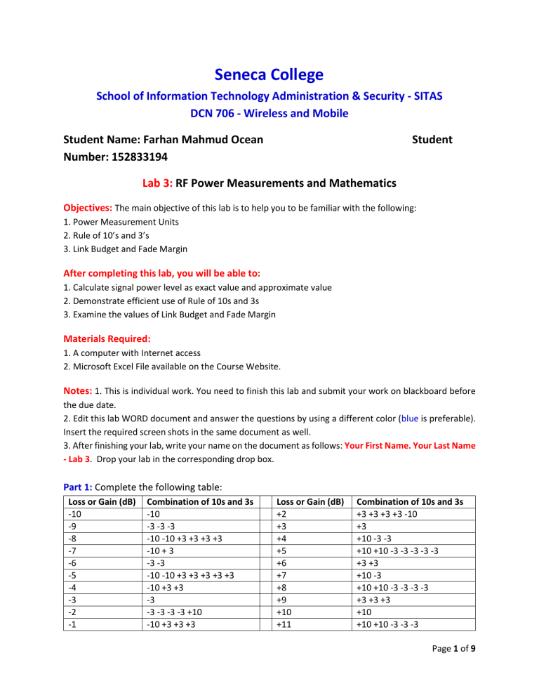
Seneca College School of Information Technology Administration & Security - SITAS DCN 706 - Wireless and Mobile Student Name: Farhan Mahmud Ocean Number: 152833194 Student Lab 3: RF Power Measurements and Mathematics Objectives: The main objective of this lab is to help you to be familiar with the following: 1. Power Measurement Units 2. Rule of 10’s and 3’s 3. Link Budget and Fade Margin After completing this lab, you will be able to: 1. Calculate signal power level as exact value and approximate value 2. Demonstrate efficient use of Rule of 10s and 3s 3. Examine the values of Link Budget and Fade Margin Materials Required: 1. A computer with Internet access 2. Microsoft Excel File available on the Course Website. Notes: 1. This is individual work. You need to finish this lab and submit your work on blackboard before the due date. 2. Edit this lab WORD document and answer the questions by using a different color (blue is preferable). Insert the required screen shots in the same document as well. 3. After finishing your lab, write your name on the document as follows: Your First Name. Your Last Name - Lab 3. Drop your lab in the corresponding drop box. Part 1: Complete the following table: Loss or Gain (dB) -10 -9 -8 -7 -6 -5 -4 -3 -2 -1 Combination of 10s and 3s -10 -3 -3 -3 -10 -10 +3 +3 +3 +3 -10 + 3 -3 -3 -10 -10 +3 +3 +3 +3 +3 -10 +3 +3 -3 -3 -3 -3 -3 +10 -10 +3 +3 +3 Loss or Gain (dB) +2 +3 +4 +5 +6 +7 +8 +9 +10 +11 Combination of 10s and 3s +3 +3 +3 +3 -10 +3 +10 -3 -3 +10 +10 -3 -3 -3 -3 -3 +3 +3 +10 -3 +10 +10 -3 -3 -3 -3 +3 +3 +3 +10 +10 +10 -3 -3 -3 Page 1 of 9 +1 +10 -3 -3 -3 +12 +3 +3 +3 +3 Part 2: In this part, you will use the Rule of 10’s and 3’s to solve three questions. Before you start solving the questions below, read the PPTs posted on the Blackboard/Course website. Q1: In Fig. 1, the access point is transmitting at 25 mW. The cable and connector between the access point and the antenna creates –2 dB of signal loss. The antenna provides 17 dBi of signal gain. Calculate the IR and EIRP values. Figure 1 dBm mW 0 1 10 10 20 100 17 50 14 25 14 dBm = 29 mW dBm mW 0 1 3 2 6 4 9 8 12 16 IR = 14 dBm – 2 dB = 12 dBm = 16 mW dBm mW 0 1 10 10 Page 2 of 9 20 100 23 200 26 400 29 800 EIRP=12dBm +17 dBi = 29 dBm = 800mW Q2: In Fig. 2, the access point is transmitting at 250 mW. The cable and connector between the access point and the antenna creates –5 dB of signal loss. The antenna provides 8 dBi of signal gain. Calculate the IR and EIRP values. Figure 2 Page 3 of 9 dBm mW 0 1 10 10 20 100 30 1000 27 500 24 250 250mW=24dBm IR=24-5=19dBm EIRP=19+8=27dBm=500mW dBm mW 0 1 10 10 13 20 16 40 19 80 IR = 19dBm=80mW Page 4 of 9 Q3: In Fig. 3, the access point is transmitting at 60 mW. The cable and connector between the access point and the antenna creates –6 dB of signal loss. The antenna provides 12 dBi of signal gain. Calculate the IR and EIRP values. Figure 3 dBm mW x 60 X -3 30 X–3-3 15 X – 6 = x – 3 -3 Page 5 of 9 dBm mW x 60 X+3 120 X+3+3 240 X -6 + 12 = x+6 = x+3+3 IR = 15mW EIRP = 240mW Page 6 of 9 Part 3: Link Budget and Fade Margin In this part you will learn about the link budget and fade margin. You will use a Microsoft Excel file to calculate a link budget and fade margin. 1. From the BB, download the file LinkBudget.xls to your computer. Open the Excel file from your computer. 2. In row 10, enter a link distance of 25 kilometers. Note that the path loss due to a 25 kilometer link is now 128 dB in the 2.4 GHz frequency. Question: How do you compare the FSPL of the three frequencies (900 MHz, 2.4 GHz, and 5.8 GHz)? Hint: See the values in the rows 12, 13, and 14 respectively. Ans. As the frequency of the radio wave rises, the attenuation of free-space path loss also rises. 3. In row 20, enter 128 for path loss in dB. 4. In row 23, change the radio receiver sensitivity to –80 dBm. Notice that the final received signal is now –69 dBm, and the fade margin is only 11 dB. 5. Try increasing the “radio transmitter output power” to see how the connection would fare and to determine how much power would be needed to ensure a fade margin of 20 dB. Ans. The radio transmitter output power = ........29...... (dBm) Question: The minimum value of radio transmitter to keep the communication successful is equal to .......22........ (dBm) You can also change the other components such as antenna gain and cable loss to ensure a fade margin of 20 dB. 6. Now, start with the default values of the Excel File and examine the effect of different parameters in the Excel file and make summary for yourself about the effect of each one of them on both the Link Budget and the Fade Margin. After that answer the following questions: A. What is the effect of increasing and decreasing the Radio Transmitter Output Power on both Link Budget and Fade Margin? Ans. Link Budget and Fade Margin rise mathematically as Radio Transmitter Output Power is increased. Link Budget and Fade Margin diminish mathematically as Radio Transmitter Output Power is reduced. Page 7 of 9 B. What is the effect of increasing and decreasing the Attenuation of Cables and Connectors on both Link Budget and Fade Margin? Ans. Increasing Reduced link budget and fading margin due to attenuation of cables and connectors to the transmit antenna. Decreasing The link budget and fading margin are increased by attenuating the cables and connectors to the transmit antenna. C. What is the effect of increasing and decreasing the Gain of Transmitting Antenna on both Link Budget and Fade Margin? Ans. Link budget and fading margin grow as transmitting antenna gain increases. Link budget and fading margin are affected by the transmitting antenna's declining gain. D. What is the effect of increasing and decreasing the Gain of Receiving Antenna on both Link Budget and Fade Margin? Ans. Link budget and fading margin rise as receiving antenna gain increases. Link budget and fading margin are affected by the receiving antenna's declining gain. E. What is the effect of increasing and decreasing the Radio Receiver Sensitivity on both Link Budget and Fade Margin? Ans. Fade margin and link budget are reduced by increasing radio receiver sensitivity. Page 8 of 9 Fade margin and link budget are increased by decreasing radio receiver sensitivity. Page 9 of 9
