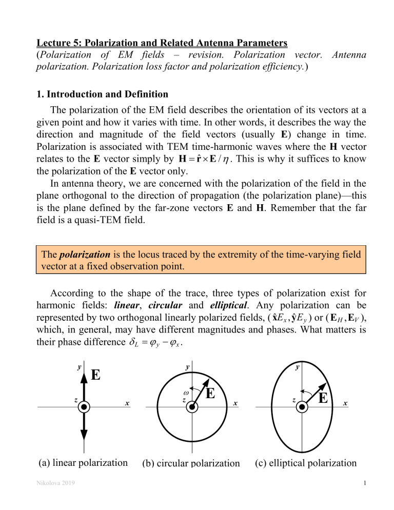
Lecture 5: Polarization and Related Antenna Parameters (Polarization of EM fields – revision. Polarization vector. Antenna polarization. Polarization loss factor and polarization efficiency.) 1. Introduction and Definition The polarization of the EM field describes the orientation of its vectors at a given point and how it varies with time. In other words, it describes the way the direction and magnitude of the field vectors (usually E) change in time. Polarization is associated with TEM time-harmonic waves where the H vector relates to the E vector simply by H = rˆ E / . This is why it suffices to know the polarization of the E vector only. In antenna theory, we are concerned with the polarization of the field in the plane orthogonal to the direction of propagation (the polarization plane)—this is the plane defined by the far-zone vectors E and H. Remember that the far field is a quasi-TEM field. The polarization is the locus traced by the extremity of the time-varying field vector at a fixed observation point. According to the shape of the trace, three types of polarization exist for harmonic fields: linear, circular and elliptical. Any polarization can be represented by two orthogonal linearly polarized fields, ( xˆ E x , yˆ E y ) or ( E H , EV ), which, in general, may have different magnitudes and phases. What matters is their phase difference L = y − x . y y E z x (a) linear polarization Nikolova 2019 z y E x (b) circular polarization z E x (c) elliptical polarization 1 • If L = n (n is integer), the field is linearly polarized, i.e., the locus traced by the tip of the E vector as time flows is a line since E(t ) = (xˆ mx yˆ m y )cos(t ) . (5.1) The magnitude of the total field is Em = mx2 + m2y . t = 0 t = 0 Ex (t ) Ex (t ) only E y (t ) t = t = E y (t ) Ex (t ) only Ex (t ) Animation: Linear Polarization, L = 0 , mx = m y Nikolova 2019 2 • If L = / 2 (90 ) and mx = m y , then the field is circularly polarized. This is evident from the fact that the magnitude of the E-field vector below remains the same at all times: E(t ) = m xˆ cos(t ) + yˆ cos(t / 2) = m xˆ cos(t ) yˆ sin(t ) (5.2) indicating that the tip of the E-field vector traces a circle as time flows. t2 = t1 + / 2 t1 Animation: Clockwise Circular Rotation • In the most general case, the polarization is elliptical. t = 0 t = / 2 Animation: Counter-clockwise Elliptical Rotation Alternatively, any type of polarization can be represented by a right-hand circular and a left-hand circular polarizations ( E LH , E RH ). [Animation] Next, we review the above statements and definitions, and introduce the new concept of polarization vector. Nikolova 2019 3 2. Field Polarization in Terms of Two Orthogonal Linearly Polarized Components The polarization of any field can be represented by the superposition of two orthogonal linearly polarized fields. Assume that locally a far-field wave propagates along the z-axis. The far-zone field vectors have only transverse components. Then, the set of two orthogonal linearly polarized fields along the x-axis and along the y-axis, is sufficient to represent any TEMz field. We use this arrangement to introduce the concept of polarization vector. The field (time-dependent or phasor vector) is decomposed into two orthogonal components: e(t ) = e x (t ) + e y (t ) E = E x + E y , (5.3) e x (t ) = Ex cos (t − z ) xˆ E x = Ex e − j z xˆ (5.4) e y (t ) = E y cos (t − z + L ) yˆ E y = E y e − j z e j L yˆ . At a fixed position (assume z = 0 ), equation (5.3) can be written as e(t ) = xˆ Ex cos t + yˆ E y cos(t + L ) (5.5) j L ˆ ˆ E = x Ex + y E y e The x-component is always assumed to have a zero phase, setting the reference for the phase of the y-component. As a result, the x-component is always real positive whereas the y-component may be complex. Case 1: Linear polarization: L = n , n = 0,1,2, e(t ) = xˆ Ex cos(t ) + yˆ E y cos(t n ) (5.6) E = xˆ Ex yˆ E y Note that the phasor vector of a linearly polarized wave is real-valued. y Ey L = 2 k 0 E y = (2k + 1) L E 0 Ey Ex Ex x x Ey Ex = arctan (a) Nikolova 2019 (b) 4 Case 2: Circular polarization: Ex = E y = Em and L = + n , n = 0,1,2, 2 e(t ) = xˆ Ex cos(t ) + yˆ E y cos[t ( / 2 + n )] (5.7) E = Em (xˆ jyˆ ) Note that the phasor of a circularly polarized wave is complex with the xcomponent being real-positive whereas the y-component is purely imaginary. E = Em (xˆ + jyˆ ) E = Em (xˆ − jyˆ ) L = − − 2n L = + t = 2 3 t = y 2 5 4 z t = t = + 2n 2 t = 3 t = 4 7 4 t = 0 x 3 4 t = t = 4 2 If +zˆ is the direction of propagation: counterclockwise (CCW) or lefthand (LH) polarization t = 2 t = t = t = y z 5 4 4 t = 0 x t = 7 4 3 2 If +zˆ is the direction of propagation: clockwise (CW) or right-hand (RH) polarization t = The sense of rotation, clockwise or counterclockwise, depends on the direction into which the observer looks. To avoid this ambiguity, in antenna engineering, the direction into which the observer looks must coincide with the direction of wave propagation. In the plot on the left, where E( z ) = Em (xˆ + jyˆ ) , if the wave propagates along −zˆ (into the plot), we have a right-hand (RH or CW) wave. In the plot on the right, where E( z ) = Em (xˆ − jyˆ ) , if the wave propagates along −zˆ (into the plot), we have a left-hand (LH or CCW) wave. Nikolova 2019 5 Vice versa, if the wave propagates along +zˆ , then the left plot shows a LH (or CCW) wave, whereas the right plot shows a RH (or CW) wave. The terms RH and LH are associated with the use of the right hand or the left hand to relate the direction of propagation to the direction of rotation of the E-field vector. The thumb of the hand has to be aligned with the direction of propagation. With this alignment, one has to determine whether it is the fingers of the right hand or those of the left hand that show properly the direction of rotation of the E-field. There is a simple rule of thumb that can be used to tell whether a wave has RH or LH sense of rotation. If the sign in the propagation factor of the wave matches the sign of the y-component in the field pahsor, then the wave is RHCP. If the signs do not match, the wave is LHCP. Assume, for example, a wave travelling along + z . The propagation factor is then e − j z . The phasor E( z ) = Em (xˆ + jyˆ ) e− j z (5.8) represents an LHCP wave. This is the case in the left plot on the previous page. On the contrary, the phasor E( z ) = Em (xˆ − jyˆ ) e − j z (5.9) represents an RHCP wave. This is the case in the right plot. For a wave travelling along − z , the propagation factor is e + j z and so E( z ) = Em (xˆ + jyˆ ) e+ j z (5.10) is an RHCP wave whereas E( z ) = Em (xˆ − jyˆ ) e + j z (5.11) is LHCP. A snapshot of the field vector along the axis of propagation is given below for an RHCP wave. Pick an observing position along the axis of propagation (see the plane defined by the x and y axes in the plot below) and imagine that the whole helical trajectory of the tip of the field vector moves along the wave vector k . Are you going to see the vector rotating clockwise or counterclockwise as you look along k ? (Ans.: Clockwise, which is equivalent to RH sense of rotation.) Nikolova 2019 6 [Hayt, Buck, Engineering Electromagnetics, 8th ed., p. 399] Case 3: Elliptic polarization The field vector at a given point traces an ellipse as a function of time. This is the most general type of polarization, obtained for any phase difference and any ratio ( Ex / E y ) . Mathematically, the linear and the circular polarizations are special cases of the elliptical polarization. In practice, however, the term elliptical polarization is used to indicate polarizations other than linear or circular. e(t ) = xˆ Ex cos(t ) + yˆ E y cos(t + L ) (5.12) j L ˆ ˆ E = xEx + yE y e Show that the trace of the time-dependent vector is an ellipse: e y (t ) = E y (cos t cos L − sin t sin L ) e (t ) e (t ) cos t = x and sin t = 1 − x Ex Ex 2 2 e (t ) e (t ) e (t ) e (t ) sin 2 L = x − 2 x y cos L + y Ex Ex E y Ey or (dividing both sides by sin 2 L ), (5.13) 1 = x 2 (t ) − 2 x(t ) y(t )cos L + y 2 (t ) , where e y (t ) ex (t ) cos(t ) cos(t + L ) = and y (t ) = . x(t ) = = E y sin L sin L Ex sin L sin L 2 Nikolova 2019 7 Equation (5.13) is the equation of an ellipse centered in the xy plane. It describes the trajectory of a point of coordinates x(t) and y(t), i.e., normalized ex (t ) and e y (t ) values, along an ellipse where the point moves with an angular frequency . Similarly to the circular polarization, the elliptical polarization can be righthanded or left-handed, depending on the relation between the direction of propagation and the sense of rotation. ey (t ) Ey no mi ) Ex ex (t ) O (2 ( xis ra B) xis ra o j ma A 2O E The parameters of the polarization ellipse are given below. Their derivation is given in Appendix I. a) major axis ( 2 OA ) 1 2 OA = Ex + E y2 + Ex4 + E y4 + 2 Ex2 E y2 cos(2 L ) 2 b) minor axis ( 2 OB ) 1 2 OB = Ex + E y2 − Ex4 + E y4 + 2 Ex2 E y2 cos(2 L ) 2 (5.14) (5.15) c) tilt angle 2E E 1 = arctan 2 x y2 cos L 2 Ex − E y 2 (5.16) A Note: Eq. (5.16) produces an infinite number of angles, τ = (arctanA)/2 n / 2 , n = 1,2,…. Thus, it gives not only the angle which the major axis of the ellipse forms with the x axis but also the angle of the minor Nikolova 2019 8 axis with the x axis. In spherical coordinates, τ is usually specified with respect to the θ̂ direction. d) axial ratio AR = major axis OA = minor axis OB (5.17) Note: The linear and circular polarizations as special cases of the elliptical polarization: • If L = ( ( / 2) + 2n ) and E x = E y , then OA = OB = Ex = E y ; the ellipse becomes a circle. • If L = n , then OB = 0 and = arctan( E y / E x ) ; the ellipse collapses into a line. 3. Field Polarization in Terms of Two Circularly Polarized Components The representation of a complex vector field as a superposition of circularly polarized components is somewhat less intuitive but it is actually more convenient in the calculation of the polarization ellipse parameters. This time, the total field phasor is represented as the superposition of two circularly polarized waves, one right-handed and the other left-handed. For the case of a wave propagating along − z [see Case 2 and Eq. (5.7)], E = ERH (xˆ + jyˆ ) + ELH (xˆ − jyˆ ) . (5.18) Here, ERH and ELH are, in general, complex phasors. Assuming a relative phase difference of C = R − L , one can write (5.18) as E = eR e jC ( xˆ + jyˆ ) + eL ( xˆ − jyˆ ) , (5.19) where eR and eL are real numbers. The relations between the linear-component and the circular-component decompositions are easily found by re-arranging (5.18) as E = xˆ ( ERH + ELH ) + yˆ j ( ERH − ELH ) (5.20) Ex Nikolova 2019 Ex = ERH + ELH E y = j ( ERH − ELH ) ERH = 0.5( Ex − jE y ) ELH = 0.5( Ex + jE y ). Ey (5.21) (5.22) 9 4. Polarization Vector and Polarization Ratio of a Plane Wave The polarization vector is the normalized phasor of the electric field vector. It is a complex-valued vector of unit magnitude, i.e., ρˆ L ρˆ L = 1. E y j L E E (5.23) = xˆ x + yˆ e , Em = E E Em Em Em The expression in (5.23) assumes a wave decomposition into linearly polarized (x and y) components, thereby the subscript L. Polarization vector in terms of RHCP and LHCP components is also used. The polarization vector defined in (5.23) takes the following specific forms in the cases of linearly, circularly and elliptically polarized waves. ρˆ L = Case 1: Linear polarization (the polarization vector is real-valued) Ey E ρˆ = xˆ x yˆ , Em Em where E x and E y are real. (5.24) Case 2: Circular polarization (the polarization vector is complex-valued) 1 ρˆ L = (5.25) ( xˆ jyˆ ) , Em = 2E x = 2E y 2 The polarization ratio is the ratio of the phasors of the two orthogonal polarization components. In general, it is a complex number: rL = rL e L E y E y e j L = = Ex Ex (5.26) Point of interest: In the case of circular-component representation, the polarization ratio is defined as E rC = rC e jC = RH . (5.27) ELH The circular polarization ratio rC is of particular interest since the axial ratio of the polarization ellipse AR can be expressed very simply as Nikolova 2019 10 AR = rC + 1 . rC − 1 Besides, its tilt angle with respect to the y (vertical) axis is simply V = C / 2 + n , n = 0, 1,... . (5.28) (5.29) Comparing (5.16) and (5.29) readily shows the relation between the phase difference δC of the circular-component representation and the linear polarization ratio rL = rLe j L : 2r (5.30) C = arctan L 2 cos L . 1 − r L We can calculate rC from the linear polarization ratio rL = rL e j L by making use of (5.14), (5.15), (5.17) and (5.28): 1 + rL2 + 1 + rL4 + 2rL2 cos(2 L ) rC + 1 . (5.31) AR = = rC − 1 1 + rL2 − 1 + rL4 + 2rL2 cos(2 L ) Using (5.30) and (5.31) allows for the switching between the representation of the wave polarization in terms of linear and circular components. 5. Antenna Polarization In general terms, the polarization of a transmitting antenna is the polarization of its radiated wave in the far zone. The polarization of a receiving antenna is the polarization of an incident plane wave, which, for a given power flux density, results in maximum available power at the antenna terminals. Mathematically, the antenna’s polarization is defined by the polarization vector of the wave it transmits and in the coordinate system where the antenna is at the origin. Here, it is important to appreciate the fact that the polarization vector ρˆ tw of a wave in the coordinate system of the transmitting antenna (the wave moves away from the origin along +rˆ t ) is the conjugate of this wave’s polarization vector ρˆ rw in the coordinate system of receiving antenna, in the coordinate system of which the wave moves toward the origin along −rˆ r ): ρˆ rw = (ρˆ tw ) . (5.32) The conjugation is without importance for a linearly polarized wave since its Nikolova 2019 11 polarization vector is real. It is, however, important in the cases of circularly and elliptically polarized waves. This is illustrated in the figure below with a RHCP wave. Let the coordinate triplet ( x1t , x2t , x3t ) represent the coordinate system of the transmitting antenna while ( x1r , x2r , x3r ) represents that of the receiving antenna. In antenna analysis, the plane of polarization is usually given in spherical coordinates by (xˆ 1, xˆ 2 ) (θˆ , φˆ ) and the third axis obeys xˆ 1 xˆ 2 = xˆ 3 , and so it is xˆ 3 rˆ . Since the transmitting and receiving antennas face each other, their coordinate systems are oriented so that xˆ t3 = −xˆ 3r ( rˆ r = −rˆ t ). If we align the axes xˆ 1t and xˆ 1r ( θˆ t = θˆ r ), then xˆ t2 = − xˆ r2 ( φˆ t = −φˆ r ) must hold in order to have xˆ t3 = −xˆ 3r ( rˆ r = −rˆ t ). This changes the sign of the x̂2 ( θ̂ ) field vector component. This leads to a change of sign in the imaginary part of the wave’s polarization vector. RHCP wave x2t x1t x1r t = 0 t = 0 kˆ = t = / 2 ρˆ tw = x3t xˆ t3 1 t (xˆ 1 − jxˆ t2 ) 2 x2r x3r t = / 2 ρˆ rw = kˆ = −xˆ 3r 1 r (xˆ 1 + jxˆ r2 ) 2 Bearing in mind the definitions of antenna polarization in transmitting and receiving modes, we conclude that in a common coordinate system the transmitting-mode polarization vector of an antenna is the conjugate of its receiving-mode polarization vector. 6. Polarization Loss Factor (Polarization Efficiency) Generally, the polarization of the receiving antenna is not the same as the polarization of the incident wave. This is called polarization mismatch. The polarization loss factor (PLF) characterizes the loss of EM power due to the polarization mismatch. The PLF is defined so that it attains a value of 1 (or Nikolova 2019 12 100%, or 0 dB) if there is no polarization mismatch, i.e., the antenna receives the maximum possible power for the given incident power density of the wave. A PLF equal to 0 ( − dB) indicates complete polarization mismatch and inability to capture power from the incident wave. Thus, (5.33) 0 PLF 1. Note that the polarization loss has nothing to do with dissipation. It can be viewed as a “missed opportunity” to capture as much power from the incident wave as possible. The polarization efficiency has the same meaning as PLF. Let us denote the polarization vector of a wave incident upon a receiving antenna as ρˆ w . In the coordinate system where the receiving antenna is at the origin, this vector describes a wave propagating along −rˆ . Let the polarization vector of the wave that the receiving antenna would produce if it were to operate in transmitting mode is ρ̂ A . Remember that, in the coordinate system where the antenna is at the origin, ρ̂ A describes a wave propagating along +rˆ . With these polarization vectors, the PLF is defined as (5.34) PLF =| ρˆ w ρˆ A |2 . Note that if ρˆ w = ρˆ A , then PLF = ρˆ A ρˆ A = 1, and we obtain the maximum possible received power at the antenna terminals. Remember that the transmitting-mode and receiving-mode polarization vectors of a wave are mutually conjugate? This means that ρˆ A is nothing but the wave the receiving antenna would generate if it were to transmit in the direction of the incidentwave propagation. Thus, the optimal polarization of the incident wave is the one that matches the polarization of the wave produced by the receiving antenna if it were to operate in transmitting mode. Here are some simple examples: 1) if ρˆ w = ρˆ A = xˆ , then PLF=1; 2) if ρˆ w = xˆ and ρˆ A = yˆ , then PLF=0; 3) if ρˆ w = ρˆ A = xˆ + jyˆ , then PLF=0; 4) if ρˆ w = xˆ + jyˆ and ρˆ A = xˆ − jyˆ ( ρˆ w = ρˆ A ), then PLF=1. Nikolova 2019 13 [Balanis, 2nd ed.] In a communication link, the PLF has to be expressed by the polarization vectors of the transmitting and receiving antennas, ρ̂Tx and ρ̂Rx , respectively. Both of these are defined in the coordinate system of the respective antenna as the polarization of its transmitted wave. However, these two coordinate systems have their radial unit vectors pointing in opposite directions, i.e., rˆRx = −rˆTx as illustrated in the figure below. Therefore, either ρ̂Tx or ρ̂Rx has to be conjugated when calculating the PLF (it does not matter which one). For example, if the reference coordinate system is that of the receiving antenna, then 2 (5.35) PLF = ρˆ Tx ρˆ Rx . The expression PLF = ρˆ Tx ρˆ Rx Nikolova 2019 2 is also correct. 14 θ̂ Rx θ̂Tx r̂Tx φ̂Tx ρ̂Tx ρˆ Rx φ̂Rx r̂Rx ρˆ Tx ρ̂ Rx Examples Example 5.1. The electric field of a linearly polarized EM wave is Ei ( x, y, z ) = xˆ Em ( x, y )e − j z . It is incident upon a linearly polarized receiving antenna at the origin, which, if in transmitting mode, would generate the field EA ( x, y, z ) = (xˆ + yˆ ) e j z , z < 0. Find the PLF. The incident wave Ei travels along + z toward the antenna at the origin. This means that it arrives from the left (on the z axis) at the Rx antenna. Since the antenna is at the origin, when it transmits, its field E A propagates along − z in accordance with the propagation factor e j z for z < 0 as indicated in the problem statement above. 2 1 1 PLF = xˆ (xˆ + yˆ ) = 2 2 PLF[dB] = 10log10 0.5 = −3 dB Example 5.2. A transmitting antenna produces a far-zone field, which is RH circularly polarized. This field impinges upon a receiving antenna, whose polarization (in transmitting mode) is also RH circular. Determine the PLF. Both antennas (transmitting and receiving) are RH-CP circularly polarized in transmitting mode. Therefore, their polarization vectors in their respective coordinate systems are: ρˆ Tx = (θˆ t − jφˆ t ) / 2 , ρˆ Rx = (θˆ r − jφˆ r ) / 2 , Nikolova 2019 15 where θˆ r = θˆ t = θˆ and φˆ r = −φˆ t = φˆ . z E r E y x The PLF is calculated as per (5.35) i.e., using the polarization vectors as defined in the coordinate systems of the Tx and Rx antennas: | (θˆ + jφˆ ) (θˆ − jφˆ ) |2 PLF =| ρˆ *Tx ρˆ Rx |2 = = 1, 4 Notice that the conjugation of ρ̂Tx simply casts it in the coordinate system of the Rx antenna. PLF[dB] = 10log10 1 = 0 . There is no polarization loss. When transmitting with an RHCP antenna in a communication link, it is best to receive with RHCP antenna. Exercise: Show that an antenna of RH circular polarization (in transmitting mode) cannot receive LH circularly polarized incident wave (or a wave emitted by a left-circularly polarized antenna). Appendix I Find the tilt angle , the length of the major axis OA, and the length of the minor axis OB of the ellipse described by the equation: Nikolova 2019 16 2 e (t ) e (t ) e (t ) e (t ) sin 2 = x − 2 x y cos + y . Ex Ex E y Ey 2 (A-1) ey (t ) Ey no mi ) O (2 ax OA xis ra Ex ex (t ) B) jor ma 2 is ( E Equation (A-1) can be written as a x 2 − b xy + c y 2 = 1 , (A-2) where x = ex (t ) and y = e y (t ) are the coordinates of a point of the ellipse centered in the xy plane; 1 a= 2 2 ; Ex sin 2cos b= ; Ex E y sin 2 1 c= 2 2 . E y sin After dividing both sides of (A-2) by ( xy ) , one obtains x y 1 a −b+c = . (A-3) y x xy y e (t ) Introducing = = y , one obtains that x ex (t ) Nikolova 2019 17 x2 = 1 c 2 − b + a 1+ 2 ) = + = = 2 . (A-4) c − b + a Here, is the distance from the center of the coordinate system to the point on the ellipse. We want to know at what values of the maximum and the minimum of occur ( min , max ). This will produce the tilt angle . We also want to know the values of max (major axis) and min (minor axis). Then, we have to solve d ( 2 ) = 0 , or d 2( a − c ) (A-5) m2 − m − 1 = 0 , where m min , max . b (A-5) is solved for the angle τ, which relates to ξmax as max = tan = ( y / x )max . (A-6) Substituting (A-6) in (A-5) yields: 2 sin sin (A-7) − 2C −1 = 0 cos cos where E y2 − Ex2 a−c . C= = b 2 Ex E y cos Multiplying both sides of (A-7) by cos2 and re-arranging results in cos2 − sin 2 + 2C sin cos = 0 . 2( x2 y2 cos(2 ) Thus, the solution of (A-7) is x 2 (1 + 2) C sin(2 ) tan(2 ) = −1 / C or 2 Ex E y cos 1 (A-8) . ; = + 2 1 2 − E2 2 E 2 x y The angles τ1 and τ2 are the angles between the major and minor axes with the x axis. Substituting 1 and 2 back in (see A-4) yields the expressions for OA and OB. 1 = arctan Nikolova 2019 18

![Hints to Assignment #12 -- 8.022 [1] Lorentz invariance and waves](http://s2.studylib.net/store/data/013604158_1-7e1df448685f7171dc85ce54d29f68de-300x300.png)

