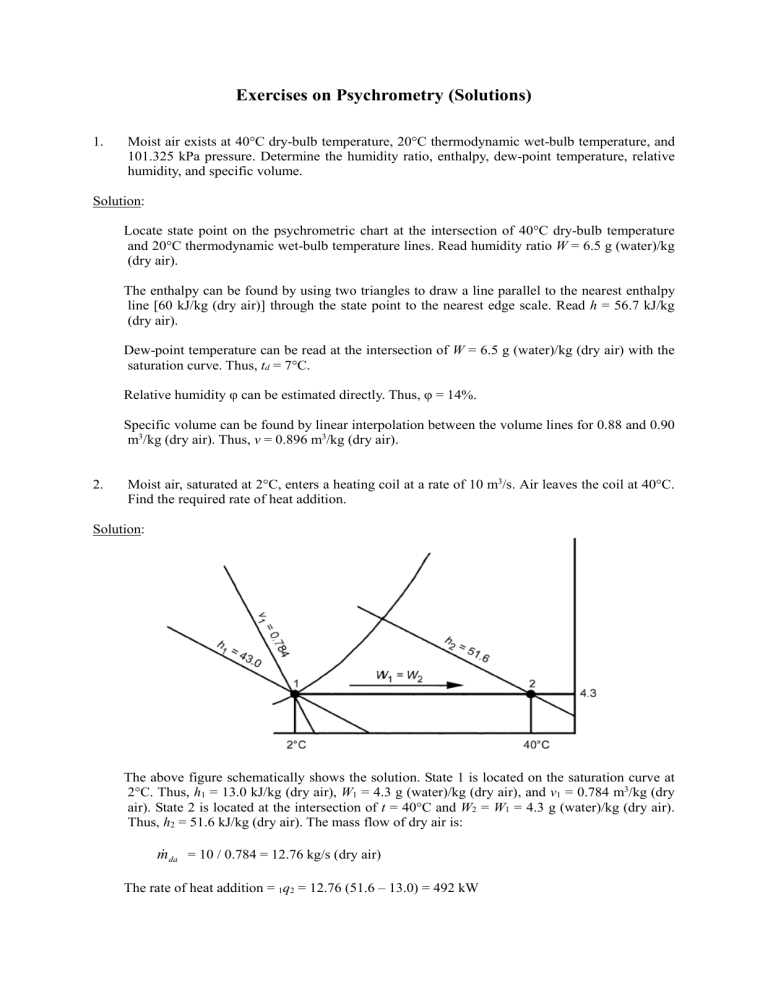
Exercises on Psychrometry (Solutions) 1. Moist air exists at 40°C dry-bulb temperature, 20°C thermodynamic wet-bulb temperature, and 101.325 kPa pressure. Determine the humidity ratio, enthalpy, dew-point temperature, relative humidity, and specific volume. Solution: Locate state point on the psychrometric chart at the intersection of 40°C dry-bulb temperature and 20°C thermodynamic wet-bulb temperature lines. Read humidity ratio W = 6.5 g (water)/kg (dry air). The enthalpy can be found by using two triangles to draw a line parallel to the nearest enthalpy line [60 kJ/kg (dry air)] through the state point to the nearest edge scale. Read h = 56.7 kJ/kg (dry air). Dew-point temperature can be read at the intersection of W = 6.5 g (water)/kg (dry air) with the saturation curve. Thus, td = 7°C. Relative humidity φ can be estimated directly. Thus, φ = 14%. Specific volume can be found by linear interpolation between the volume lines for 0.88 and 0.90 m3/kg (dry air). Thus, v = 0.896 m3/kg (dry air). 2. Moist air, saturated at 2°C, enters a heating coil at a rate of 10 m3/s. Air leaves the coil at 40°C. Find the required rate of heat addition. Solution: The above figure schematically shows the solution. State 1 is located on the saturation curve at 2°C. Thus, h1 = 13.0 kJ/kg (dry air), W1 = 4.3 g (water)/kg (dry air), and v1 = 0.784 m3/kg (dry air). State 2 is located at the intersection of t = 40°C and W2 = W1 = 4.3 g (water)/kg (dry air). Thus, h2 = 51.6 kJ/kg (dry air). The mass flow of dry air is: m da = 10 / 0.784 = 12.76 kg/s (dry air) The rate of heat addition = 1q2 = 12.76 (51.6 – 13.0) = 492 kW 3. Moist air at 30°C dry-bulb temperature and 50% rh enters a cooling coil at 5 m3/s and is processed to a final saturation condition at 10°C. Find the kW of refrigeration required. Solution: The above figure shows the schematic solution. State 1 is located at the intersection of t = 30°C and φ = 50%. Thus, h1 = 64.3 kJ/kg (dry air), W1 = 13.3 g (water)/kg (dry air), and v1 = 0.877 m3/kg (dry air). State 2 is located on the saturation curve at 10°C. Thus, h2 = 29.5 kJ/kg (dry air) and W2 = 7.66 g (water)/kg (dry air). From Table 2, hw2 = 42.11 kJ/kg (water). The mass flow of dry air is: m da = 5 / 0.877 = 5.70 kg/s (dry air) The kW of refrigeration = 1q2 = 5.70 [(64.3 – 29.5) – (0.0133 – 0.00766) 42.11] = 197 kW 4. A stream of 2 m3/s of outdoor air at 4°C dry-bulb temperature and 2°C thermodynamic wet-bulb temperature is adiabatically mixed with 6.25 m3/s of recirculated air at 25°C dry-bulb temperature and 50% rh. Find the dry-bulb temperature and thermodynamic wet-bulb temperature of the resulting mixture. Solution: The above figure shows the schematic solution. States 1 and 2 are located on the ASHRAE chart, revealing that v1 = 0.789 m3/kg (dry air), and v2 = 0.858 m3/kg (dry air). Therefore, m da1 = 2 / 0.789 = 2.535 kg/s (dry air) m da 2 = 6.25 / 0.858 = 7.284 kg/s (dry air) By comparing the proportion of the lines, Consequently, the length of line segment 1–3 is 0.742 times the length of entire line 1–2. Using a ruler, State 3 is located, and the values t3 = 19.5°C and t3 * = 14.6°C found. 5. Moist air at 20°C dry-bulb and 8°C thermodynamic wet-bulb temperature is to be processed to a final dew-point temperature of 13°C by adiabatic injection of saturated steam at 110°C. The rate of dry airflow is 2 kg/s (dry air). Find the final dry-bulb temperature of the moist air and the rate of steam flow. Solution: The above figure shows the schematic solution. From a steam properties table, the enthalpy of the steam hg = 2691 kJ/kg (water). Therefore, according to the psychrometric equation, the condition line on the psychrometric chart connecting States 1 and 2 must have a direction: ∆h/∆W = 2.691 kJ/g (water) The condition line can be drawn with the ∆h/∆W protractor. First, establish the reference line on the protractor by connecting the origin with the value ∆h/∆W = 2.691 kJ/g (water). Draw a second line parallel to the reference line and through the initial state point of the moist air. This second line is the condition line. State 2 is established at the intersection of the condition line with the horizontal line extended from the saturation curve at 13°C (td2 = 13°C). Thus, t2 = 21°C. Values of W2 and W1 can be read from the chart. The required steam flow is, m w = m da = (W2 – W1 ) = 2 × 1000 (0.0093 – 0.0018) = 15.0 g/s (steam)
