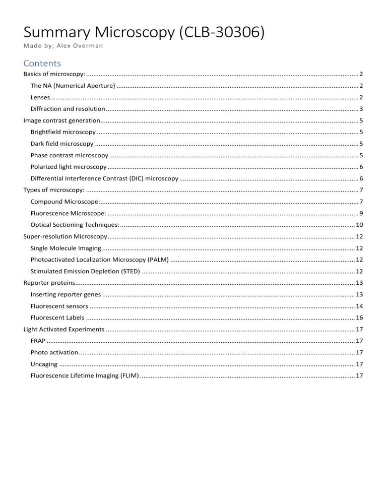
Summary Microscopy (CLB-30306) Made by; Alex Overman Contents Basics of microscopy: ........................................................................................................................................................ 2 The NA (Numerical Aperture) ....................................................................................................................................... 2 Lenses............................................................................................................................................................................ 2 Diffraction and resolution ............................................................................................................................................. 3 Image contrast generation................................................................................................................................................ 5 Brightfield microscopy .................................................................................................................................................. 5 Dark field microscopy ................................................................................................................................................... 5 Phase contrast microscopy ........................................................................................................................................... 5 Polarized light microscopy ............................................................................................................................................ 6 Differential Interference Contrast (DIC) microscopy .................................................................................................... 6 Types of microscopy: ........................................................................................................................................................ 7 Compound Microscope: ................................................................................................................................................ 7 Fluorescence Microscope: ............................................................................................................................................ 9 Optical Sectioning Techniques: ................................................................................................................................... 10 Super-resolution Microscopy .......................................................................................................................................... 12 Single Molecule Imaging ............................................................................................................................................. 12 Photoactivated Localization Microscopy (PALM) ....................................................................................................... 12 Stimulated Emission Depletion (STED) ....................................................................................................................... 12 Reporter proteins............................................................................................................................................................ 13 Inserting reporter genes ............................................................................................................................................. 13 Fluorescent sensors .................................................................................................................................................... 14 Fluorescent Labels ...................................................................................................................................................... 16 Light Activated Experiments ........................................................................................................................................... 17 FRAP ............................................................................................................................................................................ 17 Photo activation .......................................................................................................................................................... 17 Uncaging ..................................................................................................................................................................... 17 Fluorescence Lifetime Imaging (FLIM) ........................................................................................................................ 17 Basics of microscopy: The lens equation: 1/f = 1/s + 1/s’ Magnification: y’/s = s’/s F: focal length s and s’: object and image distances y: object size, y’: image size To calculate your magnification: ..x objective lens * ..x eyepiece lens = magnification ..mm focal length tube lens / ..mm focal length objective lens = magnification The NA (Numerical Aperture) The NA is a measure of the angles of light that can be collected by a lens (max of 1 when no immersion medium is used). Higher NA lenses collect more light and form less noisy images. NA = n sin μ where n is the refractive index of the medium and μ is half the angle of the collection cone. Lenses Immersion lens: water or oil immersion increases the numerical aperture Rays coming from the object may become reflected between the coverslip and air. These rays are not collected for image formation, but liquid immersion prevents this. Oil: n=1.516. So, a lens with NA = 0.95 will result in a 0.95*1.516 NA = 1.45 Plan designation lens: corrected for spherical aberration Spherical aberration is when parallel light rays that travel close and far away from the optical axis are not focuses to the same point. Therefore, the image appears blurred. Achromat objective lens: correct for chromatic aberrations A lens with chromatic aberration is made of a material with a wavelengthdependent index of refraction. Therefore, it refracts different colours differently So, plan achromats are corrected for both spherical and chromatic aberrations. Image brightness increases with the square of the NA value of the objective lens, increases with the use of oil-immersion, and decreases with image magnification. Diffraction and resolution Diffraction is the bending of light waves around small objects and openings like water waves. For this fundamental reason there is a limit to the size of individual features that can be distinguished. A parallel beam forms a diffraction-limited airy pattern, which is about 200 nm in size. The radius of the first dark ring in the airy pattern, and thus the resolution, equals RAiry = 1.22 * λ / (NAcondenser + NAobjective). For top quality lenses this equals about 1.22 * 530 nm / (1.45+1.45) = 223 nm. The better the NA, the better the resolution. The resolution is inversely proportional to the wavelength, so small wavelengths like blue light give a good resolution. The Rayleigh criterion: Two objects can just be resolved if the spacing is equal to the radius of the airy disk, which is about 200 nm Pixel size The optimal spacing of pixels is; not too large to cause loss of detail, but not too small to collect inadequate signal. The Nyquist criterium states that the pixel size that optimizes signal per pixel, whilst maintaining fine resolvable detail is around half the radius of the airy pattern (half the resolution of a microscope). If your pixels are too small, a process called pixel binning can be used to sum the signal of a group of pixels. It will however decrease resolvable detail. Koehler illumination: Kohler illumination illuminates the sample evenly and allows control over illumination angles. The light source is focused by an additional lens in the focal plane of the condenser lens. This way each point of the lamp generates a parallel beam of light that illuminates the whole sample but under a different angle. Closing the condenser aperture decreases the range of angles at which the sample is illuminated. Field diaphragm and condenser lens The field aperture controls the size of the illuminated area The condenser aperture selects the angles under which the sample is illuminated Image contrast generation Brightfield microscopy This type of microscopy relies on the local change of colour/intensity of pigmented areas in the final image. In general, the contrast is low, but this can be improved by using histological stains. Dark field microscopy In dark field microscopy the sample is illuminated with a hollow cone of light because a stop in the back focal plane of the condenser blocks light under small angles. If no sample is present the rays will continue in a straight line and no illumination will reach the objective lens. Only light that is scattered by a sample will contribute to image formation. A disadvantage is that this technique is very sensitive to stray dust and other artefacts that deflect light. Phase contrast microscopy Illumination with a hollow cone of light will be scattered by a sample which causes about ¼ phase shift change. A phase plate in the objective lens imposes an additional ¼ phase shift on the scattered light only. Destructive interference then locally darkens the image to generate contrast. This technique is often used for imaging tissue culture cells as it visualizes “phase dense” objects. Limitations are a halo around the specimen, and its not usable for thick specimens. Polarized light microscopy A first polarizer selectively passes only one angle of polarization. A second polarizer rotated 90 degrees will block this light completely. Birefringent (the angle of light refraction depends on the polarisation direction of the light) samples however can rotate the polarization axis, thus an image is formed. Differential Interference Contrast (DIC) microscopy DIC combines concepts from polarization and phase contrast microscopy. Samples do not need to be birefringent. The technique detects a phase change that is generated between two light rays that take a slightly different path through a sample. A phase change is generated when one of the rays travels through an object with a higher index of refraction. This phase change is converted to a change in direction of polarization by a Wollaston prism. This change in polarization is then detected similarly as in a polarized light microscope. Because the phase delay can be by either of the rays the phase difference can result in both a higher and lower intensity. So as a result the image has a shadow cast appearance with dark and bright edges specifically at boundaries of different materials. Summary: Bright Field Microscopy: Simplest form of microscopy, is frequently used in combination with histological stains to generate contrast. Dark Field Microscopy: It uses the phase of light to generate image contrast. It requires the NA of the objective lens to be smaller than the NA of the condenser lens. Phase Contrast Microscopy: It relies on destructive interference of scattered and unscattered light rays with different phases. It relies on a phase shift of 90 degrees when light Is scattered. Polarized Light Microscopy: Generates contrast on samples that are birefringent. DIC Microscopy: Generates contrast depending on the size and direction of the local gradient in refractive index within the sample. It uses two Wollaston prisms to generate and re-combine two spatially-shifted light rays that are orthogonally polarized. Wollaston prisms are only used for DIC microscopy. FRAP Studies: the rate of Fluorescence Recovery After Photobleaching. Types of microscopy: Compound Microscope: It uses a two-step magnification where the total magnification is Mobjective x Meyepiece . The field aperture’s function is to prevent stray light (photobleaching) by limiting the illuminated area of the sample to the size of the observed area (field of view). A condenser lens collects and focusses light from the illumination source onto the specimen. Infinity optical system: It uses two lenses but there is no intermediate image. The object is placed in the focal plane of the objective. This way each point of the object forms a parallel bundle of light. A tube lens forms a real image on a camera sensor where the magnification is ftube / fobjective . In the infinity space of parallel light bundles auxiliary optical components can be introduced without much effect on the image formation. Fluorescence Microscope: A molecule is placed in an excited state by absorption of a photon. When the molecule decays back to ground state a photon with less energy is emitted (less energy = longer wavelength = red shifted). This shift in wavelength equals the Stokes’ shift. A basic fluorescence microscope needs a light source that emits colours, an excitation filter that selects a usable wavelength, and an emission filter that blocks the excitation light and passes fluorescence light to the camera. Fluorescence’s advantages are; sensitive, specific, multiparameter (intensity, bursts, polarization, lifetime), living cell and dynamics. Disadvantages are; labelling and introduction into the cell, phototoxic effect, sample thickness and fluorophore disturbance. Different light sources: Halogen/Tungsten lamp: light intensity is distributed over a continuous spectrum. Excitation filters are used to select specific excitation colours. Gas discharge lamp (Mercury, Xenon arc): light spectrum contains intense peaks at certain wavelengths. LEDs: Narrow wavelength bands can be produced, but each fluorophore requires a different specific LED. LASERS: High intensity in a single wavelength, so no filter required to block unwanted colours. Epi-fluorescence microscope: Excitation light does not shine in your detector and background light is efficiently blocked. The objective is now used for both illumination and observation Resolution = Dmin = 1.22 * λ / (NAcondenser + NAobjective) = Dmin = 1.22 * λ / 2 NAobjective The limitation of fluorescence is the inevitable photo bleaching that takes place due to excitation. Besides bleaching, also quenching decreases intensity of fluorescence. Quenching is the transfer of energy to nearby acceptor molecules through various mechanisms. The thickness of an in-focus slice is equal to the z resolution of a microscope = dz = 2λn/NA2 Optical Sectioning Techniques: Confocal Laser Scanning Microscopy (CLSM) The principle was proposed by Minski (1955) and encompasses the use of spatial filtering techniques to eliminate out-of-focus light. By placing an aperture (pinhole) in the image plane, the out-of-focus light cannot reach the detector. This enhances the signal to noise ratio (enhanced contrast), allows for better sectioning (thinner slices in zdirection) and improves axial and lateral resolution. In a conventional wide-field fluorescence microscope a mercury lamp illuminates the entire specimen. A confocal microscope uses a parallel laser beam that is focused into a small diffraction spot. Scan mirrors in the excitation path can move this spot for point-by-point measurements. In this way an image is generated of the fluorescence emitted from a horizontal plan at a certain depth inside the sample, called optical sectioning. Confocal microscopy can create 3D-images of the structure but also show dynamics of cellular processes. Image Deconvolution A stack of images is taken at different heights, which are combined whilst applying deconvolution to redistribute image intensity over the image stack to remove out of focus blur. The drawback is that fluorophores bleach quickly. Even if only a single plane is required one still needs to acquire a z-stack to apply the deconvolution algorithm. Also does not work with life cells because of movement during imaging. Spinning Disk Microscopy (SDM) A disk with microlenses focuses an excitation beam onto the holes in the second disk; the pinhole or Nipkow disk. An array of pinholes on the Nipkow disk are spaced apart just enough such that fluorescent light generated does not mix with neighbouring holes. Each location on the sample is illuminated about 1000 times per second, so illumination takes place not once but multiple times during a camera exposure of roughly 100ms. Compared to CLSM there is a lower local excitation intensity, so bleaching is minimized. It is however less flexible for FRAP/FRET and has a fixed pinhole size. Multi-photon Microscopy Instead of using one light source with a certain wavelength to excite a fluorophore one can use two lower-energy photons at half the energy (e.g. 2x 1000nm vs 1x 500nm), but only if the two photons arrive nearly at the same time. Such an event’s likeliness increases with the square of the excitation intensity. The advantage is that higher wavelength penetrates deeper into tissues compared to visible light. No excitation and photobleaching takes place in out-of-focus planes. You do however need more complex pulsed lasers that deliver high instantaneous intensity. Also, photobleaching is accelerated in the in-focus plane. Total Internal Reflection Microscopy (TIRF) A sample is illuminated through the objective by a shallow angle light ray that reflects at the cover glass – water interface. Above a critical incident angle (about 62 degrees) light is fully reflected. An evanescent light field however penetrates about 100 nm into the water. Consequently, only fluorophores near the interface are excited, and high contrast is achieved because there is no fluorescence from other planes in the sample. Selective Plane Illumination Microscopy (SPIM) One plane of the sample is illuminated by a thin light sheet coming from the side. Little out-of-focus light is present because other planes are not illuminated. The technique can be combined with image deconvolution to further increase resolution. Fluorophores in other planes do not photobleach. Summary: Super-resolution Microscopy Single Molecule Imaging Whilst it is not possible to resolve single molecules that are close together, it is possible to localize single fluorophores precisely if their spacing is sparse. Emitted light is distributed over several neighbouring pixels, but the centre can be estimated with an accuracy smaller than the individual pixel size. Up to 1nm accuracy can be achieved if sufficient photons are detected. The theoretical position accuracy = Diffraction limited resolution / √N Photoactivated Localization Microscopy (PALM) Fluorophores like the photoactivatable PA-GFP can be switched on by a specific wavelength. Single activated fluorophores in the on-state are detected with light of a different wavelength, fluorophores in the offstate are not visible. The temporarily activated fluorophores are imaged and their positions can be determined with ~20nm accuracy. The overall image is reconstructed with a computer from the positions obtained from hundreds of imaging cycles. This however requires the sample to be completely immobile, but faster cameras improve on this. Stimulated Emission Depletion (STED) Fluorophores can be stimulated to decay quickly to their ground state using light at the emission wavelength. In STED microscopy fluorophores are first excited in a confocal laser spot. Directly after this the confocal volume is illuminated with a doughnut-shaped beam profile after which only the fluorophores in the centre of the confocal volume remain in their excited state. These fluorophores decay and emit light which is detected. Because the detected light originates from a spot smaller than the diffraction limit, up to a 10-fold improvement in resolution is achieved. The setup is complicated however, and photo bleaching is rapid. Reporter proteins Colour stain as reporter -> enzyme E.G. The bacterial lacZ gen with blue pigment Bioluminescence reporter -> enzyme E.G. The bacterial luciferase (LUX), the firefly luciferase (ffLUC) or Aequorin LUC is good for promotor dynamics Fluorescence reporter -> structural protein E.G. Green Fluorescent Protein (GFP) or tdTomato GFP is good for cellular resolution promotor activity, subcellular localisation studies or protein stability studies. Inserting reporter genes Transient transformation (100-1000000 gene copies) This quick but temporary implementation is transitory and will thus only last a short time. Agroinfiltration; The leaf is infiltrated with activated A. tumefaciens solution carrying the reporter construct. The pathogen can transfer Ti-DNA to cells of the infiltrated tissue. The Ti-Dna is expressed in the cells but will be degraded after a few hours/days. Particle bombardment; Gold particles are coated with DNA containing the reporter construct. The plant tissue is bombarded with the coated particles. Cells that survive can express the introduced DNA Transfecting protoplasts; Protoplasts are plant cells without a cell wall. The protoplasts are suspended in a solution with the reporter DNA construct. Temporary disruption of the plasma membrane via chemical treatment, electro or heat shock will allow many copies of the reporter DNA to diffuse into the nucleus of the cell and be transcribed. Stable transformation (1-10 gene copies) Integrating the reporter gene into the genome is time-consuming but it has advantages. It has both the ability to retain a reporter gene for multiple generations, and it also has the ability to cross in order to generate double labelled plant lines. Agrobacterium tumefaciens is a plant pathogen that injects its Ti-plasmid into the plant cell. It integrates at random into chromosomal DNA to reprogram plant cells. By engineering the pathogen, it is possible to insert modified pieces of DNA. Insertion is random however, so your construct can disrupt genes if integrated at the wrong position. Heterochromatin is tightly packed DNA, Euchromatin is loosely packed DNA. Integration into heterochromatin results in no transcription. This can however be prevented by using Matrix Attachment Regions to flank your reporter gene which connects chromatin loops with histones. Fluorescent sensors FRET based biosensors: FRET: Föster Resonance Energy Transfer is the transfer of energy from an excited chromophore to a neighbouring chromophore. FRET is good for interaction studies between two binding domains that alter spacing by a binding ligand, or for two proteins that interact. The energy transfer is non-radiative and through space. The prerequisite for FRET is R0 = the critical distance between donor and acceptor where energy transfer is 50%. R0 = 0.0211 x (K2QD J n-4 )1/6 (nm) K2 = the dipole orientation, when random it’s 2/3 QD = the Quantum yield of the Donor (0<QD<1) J = the spectral overlap between donor emission and acceptor absorbance N = refractive index (1.4 inside fixed cells) The efficiency transfer is inversely proportional to the sixth power over the distance R between the Donor and the Acceptor. In practice the formula to calculate FRET = If-BTd*Id-BTa*Ia If = Intensity FRET channel (acceptor channel) with donor excitation wavelength Id = Intensity Donor channel with donor excitation wavelength Ia = Intensity Acceptor channel with acceptor excitation wavelength BTd = Bleed through from donor BTa = Bleed through due to direct excitation of acceptor FRET by acceptor photo-bleaching Calcium sensor Aequorin + Calcium generates an excited aequorin protein. By coupling a GFP to aequorin energy is transferred from aequorin to the GFP, emitting green light. As such aequorin-GFP can act as a calcium sensor. Bimolecular Fluorescence Complementation (BiFC) The association of fluorescent protein fragments that are attached to components of the same macromolecular complex. Auxin Sensor DR5 Auxin is a plant hormone with response factor ARF. ARFs function by binding auxin response elements, thereby changing transcription. A site directed mutation of AuxRE = DR5. This DR5 can be coupled to form DR5:GUS / DR5:GFP auxin reporters Green Fluorescent Protein Can reveal both promotor activity and protein localization. Potential GFP artefacts: If GFP protein blocks the signal peptide there is no normal localisation. Expression level of protein should not saturate transport routes within the cell. GFP is about 240 amino acids in size so it might change diffusion/transport of the target protein. It might also block the catalytic centre of the target protein. Fluorescent Labels Intrinsic fluorophore + no labelling & purification steps + no extension of molecule - low quantum yield - sensitive to photobleaching - selectivity Chemical dye + high quantum yield - labelling & purification steps - sensitive to environment - sticking to intracellular components Green fluorescent protein + ‘genetic’ labelling, no purification steps + high quantum yield + protected from environment - size Quantum dots + photostable + different beads excited at one wavelength + sharp emission bands + high extinction coefficient + size Ratio-probes Easily implemented Fast (suitable for live-cell imaging) Accurate spatio-temporal information Not quantitative (relative probe concentration) Independent of: Probe concentration Light intensity Photobleaching Light Activated Experiments FRAP Fluorescence Recovery After Photobleaching is a technique to look at fluorescence recovery after photobleaching in a subpopulation of molecules. Fluorophores within a small region are quickly photobleached with a focused laser beam. The subsequent exchange of fluorophores with the surrounding non-bleached region is imaged using low laser power. Apart from diffusing, molecules may reversibly bind to cellular targets. E.G. a fluorescently-tagged transmembrane protein at the nuclear envelope binds to the lamin cytoskeleton that supports the membrane. The mobility of the transmembrane protein is now jointly determined by the average lifetime of the bond to lamin and its diffusion speed in the membrane. If the timescale of diffusion is fast compared to the timescale of protein-target dissociation, then the fluorescence recovery timescale is a direct measure for bond (off-rate=1 / recovery timescale) Photo activation A mutated version of GFP can be photo-activated by UV light. The excitation spectrum changes after activation and green light is now emitted upon blue light excitation. Uncaging With uncaging a covalent bond is broken by UV light. This results in an activated form of the molecule. After uncaging the cellular response to the activated molecule can be imaged. An example is ATP. Fluorescence Lifetime Imaging (FLIM) Relaxation of excited molecules take place with a certain probability based on the radiative and non-radiative decay rates. Different molecules have different exponential decay rate of fluorescence, which is the basis for FLIM. Fluorescence lifetime imaging is based on differences in excited state decay rates from a fluorescent sample. The advantages are that the measure is absolute, an intrinsic property, independent of probe concentration or laser intensity, and it’s sensitive to the environment.
