IRJET- Automatic Propelled Mini Solar Tractor for Small Scale Farming

International Research Journal of Engineering and Technology (IRJET)
e-ISSN: 2395-0056
Volume: 06 Issue: 02 | Feb 2019 www.irjet.net p-ISSN: 2395-0072
Automatic Propelled Mini Solar Tractor for Small Scale Farming
S. Jaanaa Rubavathy
1
, M. Sathyan
2
, S. Chaitanya Karthik
3
, S. Arunan
4
1
Assisstant Professor, EEE Department, Jeppiaar SRR Engineering College, Padur, Chennai-600 103.
2,3,4
Final Year Student, EEE Department, Jeppiaar SRR Engineering College.
-----------------------------------------------------------------------***--------------------------------------------------------------------
Abstract- Farming is the traditional method of agriculture it’s the time to modernize the traditional method to modern trends of method by the use of recent technologies. With the increasing economy of present trends leads to sudden rise of labor cost and unpredicted situations of climatic conditions in the working nature. In order to avoid the losses in the situation, it’s time to overcome by automation in these techniques. The method of overcoming the non-renewable sources consumption like coal, fossil fuel by the alternative consumption of renewable sources like photovoltaic cell, the direction control is by means of ultrasonic sensors technology.
The typical challenge to face in real-time is high combustion rating in diesel tractor, this is obtained by proper utilization of generated sources by combination of hybrid power (AC and
DC). The navigation technology by means of controller to avoid human control.
The implementation design in a simplified manner by means of parental logic control of providing the input.
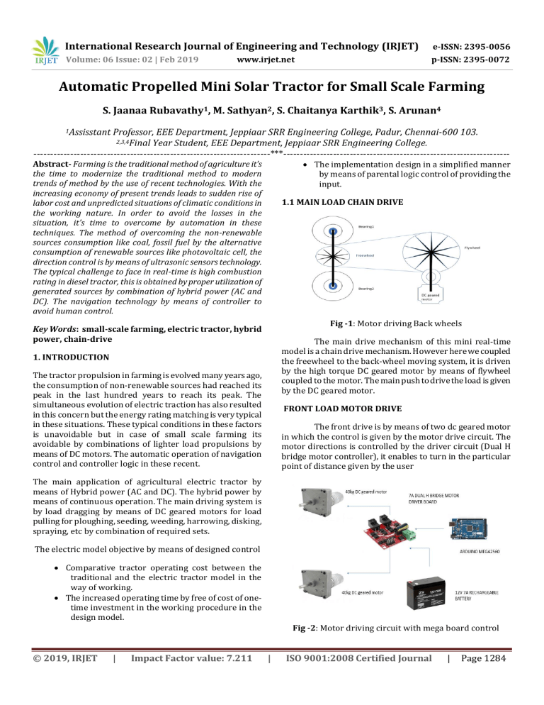
1.1 MAIN LOAD CHAIN DRIVE
Fig -1 : Motor driving Back wheels
Key Words : small-scale farming, electric tractor, hybrid power, chain-drive
1. INTRODUCTION
The main drive mechanism of this mini real-time model is a chain drive mechanism. However here we coupled the freewheel to the back-wheel moving system, it is driven by the high torque DC geared motor by means of flywheel coupled to the motor. The main push to drive the load is given by the DC geared motor.
The tractor propulsion in farming is evolved many years ago, the consumption of non-renewable sources had reached its peak in the last hundred years to reach its peak. The simultaneous evolution of electric traction has also resulted in this concern but the energy rating matching is very typical in these situations. These typical conditions in these factors is unavoidable but in case of small scale farming its avoidable by combinations of lighter load propulsions by means of DC motors. The automatic operation of navigation control and controller logic in these recent.
FRONT LOAD MOTOR DRIVE
The front drive is by means of two dc geared motor in which the control is given by the motor drive circuit. The motor directions is controlled by the driver circuit (Dual H bridge motor controller), it enables to turn in the particular point of distance given by the user
The main application of agricultural electric tractor by means of Hybrid power (AC and DC). The hybrid power by means of continuous operation. The main driving system is by load dragging by means of DC geared motors for load pulling for ploughing, seeding, weeding, harrowing, disking, spraying, etc by combination of required sets.
The electric model objective by means of designed control
Comparative tractor operating cost between the traditional and the electric tractor model in the way of working.
The increased operating time by free of cost of onetime investment in the working procedure in the design model.
Fig -2 : Motor driving circuit with mega board control
© 2019, IRJET | Impact Factor value: 7.211 | ISO 9001:2008 Certified Journal | Page 1284
International Research Journal of Engineering and Technology (IRJET)
e-ISSN: 2395-0056
Volume: 06 Issue: 02 | Feb 2019 www.irjet.net p-ISSN: 2395-0072
MOTOR CONTINOUS SUPPLY
To enhance the working time the continuous supply is given to the motor by means of means of Hybrid power of AC supply is converted into DC by means of Rectifier to maintain the constant supply in case of first charging dramatic conditions. The first charging condition is designed by the renewable source like the systematic flow in the below shown figure.
Fig -3 : Motor driving supply source
Table -1: Components Rating
Driving components
MOTOR
DC geared
Motor (Front)
DC Geared
Motor(Back)
PROPOSED SYSTEM
VOLTAGE CURRENT TORQUE
12V 7A 40kg
90v 1.14A 98lbs(44.3
kg)
The proposed system is to overcome the manual control of operation by automatic means of control and hybrid power for continuous operation. It simplifies work in a simple manner with less efforts of providing the input in meters only.
The mechanical assembly section consists of sequential arrangement of various sections of frame installation in which the place of essential components is the vital task in the working with the several loads of installation in weight balanced manner in a proper working place of usage.
Fig -5: Components embedded drive system
RUNNING TIME CALCULATION
The running time calculation of motor driving the load
The motor we have installed is a DC geared motor
Output Power=90*1.14=100watts
Storage battery=2*(12V 18 ah battery)
Total power in batteries, the two batteries in series.
Total output voltage =12+12=24V.
Total output power in two batteries
=24*18A=432WATTS.
The motor running time =432/100=4hrs.
And the total recharging is done simultaneously by the solar panel, So the working elapsed in a linear manner.
SOLAR PANEL CALCULATION FOR MOTOR
INSTALLATION
Polycrystalline panel of economic price with satisfying efficiency in working, here we use 100 watts panel is manipulated for charging battery.
100 watts solar panel rating
Open circuit voltage=17V
Short circuit current=8.33A
The total output power=100Watts
Fig -4 : The working prototype with PV panel installed
© 2019, IRJET | Impact Factor value: 7.211 | ISO 9001:2008 Certified Journal | Page 1285
International Research Journal of Engineering and Technology (IRJET)
e-ISSN: 2395-0056
Volume: 06 Issue: 02 | Feb 2019 www.irjet.net p-ISSN: 2395-0072
The input power is of variable we can use both 12V/24V, here we are using 12V panel.
The input power to charge controller is of 100 watts and the charge controller enables to continuous charging.
Graph1: Current-voltage and power-voltage characteristics - various irradiance levels
Solar panel ratings NAVIGATION CONTROL
Maximum Power
Tolerance
Open Circuit
Voltage
Short Circuit
Current
Maximum Power
Voltage
Maximum Power
Current
Module
Efficiency
Solar Cell
Efficiency
Dimensions
Weight
100W
± 3%
22V
6.06A
18V
5,56A
14,9%
17,2%
1320mm x 520mm x 30mm
8kg
PWM CHARGE CONTROLLER RATING CALCULATION
The output power from the solar panel is of 12V, so our main requirements of the charge controller is to get the panel input of 12V and the requirement to charge 24V 18ah battery(432watts).
The main requirement is to provide the increased output rating charge controller to enhance the safety for the controller
So, we provide the 24V 20A charge controller at the output terminal to charge the recharging battery. The total output power safety is 24V*20A with additional safety of 520watts rating.
Fig -6: navigation control mechanism
The total proposed system is controlled by the ultrasonic sensor by proper triggering of the sensors to navigation control.
FRONT MOTOR DRIVER CIRCUIT
This is an ultra-small low-profile dual DC motor driver for space constraint projects, capable of deliver high power of up to 7A per output channel. It uses similar logic as the L298 motor driver, where you control the driver with 3 signal pins
(IN1, IN2, ENABLE). This motor driver is driven by high power MOSFET, with the control signals opto-coupler isolated to protect any delicate circuitry and ground loop issues. With this driver we can drive with both 3.3V and 5V logic.
© 2019, IRJET | Impact Factor value: 7.211 | ISO 9001:2008 Certified Journal | Page 1286
International Research Journal of Engineering and Technology (IRJET)
e-ISSN: 2395-0056
Volume: 06 Issue: 02 | Feb 2019 www.irjet.net p-ISSN: 2395-0072
Specifications: AUTHORS
Supply Voltage: 7 ~ 24 VDC. (Limit: 6.5 ~ 27VDC).
Control signal Level (Compatible 3.3V/5V)
Logic High (H): DC 3.0 ~ 6.5V
Mrs. S.Jaanaa Rubavathy,
Assisstant professor,
Jeppiaar Srr engineering college,
Padur, Chennai-603103.
Logic Low (L): DC0 ~ 0.8V
Output Channel: 2.
Control signal current: 3 ~ 11 mA (Each route).
Maximum continuous operating current: 7A.
M. Sathyan,
Final year,
Jeppiaar srr engineering college.
Padur, Chennai-603103.
Peak current: 50A.
PWM Speed Control: 0~10KHz.
Minimum valid Pulse Width: 5us.
S. Chaitanya karthik,
Final year,
Jeppiaar srr engineering college.
Padur, Chennai-603103.
Working Temperature: -25 ~ 85 °C
Mounting Hole: M3.
Dimension (LxWxH): 55 x 55 x 13(mm).
Weight: 32g.
S. Arunan,
Final year,
Jeppiaar srr engineering college.
Padur, Chennai-603103.
3. CONCLUSIONS
Thus, the real time working semi-real time model enables us to work in a fine environment of real time working world to achieve an initialisation in an automation to fine working culture.
The automation totally avoids the labour cost in the system of management and enables to reduce the labour cost, to increase the yield in a marginal scale in a small-scale family farming design architecture.
It is also used in large scale farming in a satisfied manner in case of typical situations of working management.
It saves an amount in a marginal price. Small investments to save to large amount initialization in a proper manner.
REFERENCES
[1]
International Energy Agency, Global EV outlook 2017, ©
OECD/IEA, 2017, Page 14, Available on: https://www.iea.org/publications/freepublications/pu blication/Gl obalEVOutlook2017.pdf, acces 12.13.2017
[2]
Islam, TaoufIkul; Awal, M.Abdul, "EffIcient load and charging method for solar powered home lighting system of Bangladesh," Developments in Renewable
Energy Technology (ICDRET), 2014 3rd International
Conference on the , vol., no., pp.1 ,3, 2931 May 2014
© 2019, IRJET | Impact Factor value: 7.211 | ISO 9001:2008 Certified Journal | Page 1287


