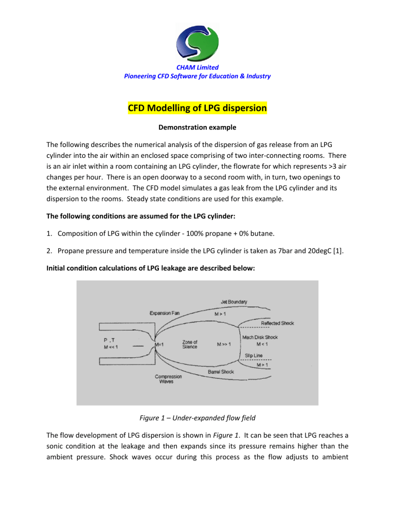
CHAM Limited Pioneering CFD Software for Education & Industry CFD Modelling of LPG dispersion Demonstration example The following describes the numerical analysis of the dispersion of gas release from an LPG cylinder into the air within an enclosed space comprising of two inter-connecting rooms. There is an air inlet within a room containing an LPG cylinder, the flowrate for which represents >3 air changes per hour. There is an open doorway to a second room with, in turn, two openings to the external environment. The CFD model simulates a gas leak from the LPG cylinder and its dispersion to the rooms. Steady state conditions are used for this example. The following conditions are assumed for the LPG cylinder: 1. Composition of LPG within the cylinder - 100% propane + 0% butane. 2. Propane pressure and temperature inside the LPG cylinder is taken as 7bar and 20degC [1]. Initial condition calculations of LPG leakage are described below: Figure 1 – Under-expanded flow field The flow development of LPG dispersion is shown in Figure 1. It can be seen that LPG reaches a sonic condition at the leakage and then expands since its pressure remains higher than the ambient pressure. Shock waves occur during this process as the flow adjusts to ambient conditions. Both the pressure and temperature drop whilst the velocity increases rapidly. Finally, the flow adjusts to the atmospheric pressure and a sonic region appears, known as the “Mach disk.” A CFD analysis of the near field flow from the LPG leak requires a very fine mesh in the wake/shock region as it adjusts to atmospheric pressure. As the required aim of this example is the dispersion of LPG over a comparatively large domain, and the wake/shock region is not of primary interest, the sonic condition is calculated and the source of LPG release positioned at the point of the Mach disk location. An ideal gas equation has been used to calculate the inlet conditions of LPG at the Mach disk location. The location of the Mach disk is estimated through Miller's empirical model. CFD Model Description The CFD model shown in Figure 2 was built using VR-Editor. Boundary Conditions: The mass flow inlet of 0.5kg/sec is located at the Mach disk. A blockage is positioned behind the Mach disk (which, in reality, is filled by LPG.) This approach neglects any entrapment of air surrounding the pipe in the small zone occupied by this blockage. The velocity of air entering through the room is set to 0.45m/sec (and equates to an air change of 3.2/hr). The window and door are defined as openings to ambient pressure and temperature of 20degC. Conservation and Transport Equations: PHOENICS solves for continuity, three momentum equations, static temperature, turbulent kinetic energy and its rate of dissipation. The effect of buoyancy is also considered. Fluid properties: A mixture model has been considered, made up of air and LPG. Figure 2 - Isometric view of room created in VR-Editor Results: Figure 3 - Velocity contours – Side View Figure 4 - Contours of volumetric concentration 10% to 100% - Side View Figure 5 - Velocity contours – Isometric View Figure 6 - Contours of volumetric concentration 10% to 100% - Isometric View Figure 7 - Contours of volumetric concentration 0% to 50% - Isometric View Figure 8 - Iso-surface contour at surface value of 20% Figure 9- Iso-surface contour at surface value of 30% Figure 10 - Iso-surface contour at surface value of 40% Figure 11 - Iso-surface contour at surface value of 42% In Figure 11, it can be noticed that the LPG leaves the source as a jet, mixes with air and settles down to the floor as its density is greater than air. Hence the concentration of LPG is greater near the floor than the ceiling and the volume of air present above the cylinder is higher. The maximum volume fraction in the second room is about 40%. Gas detectors are commonly installed in order to identify leaks that could otherwise lead to catastrophes such as explosions and fires. The preliminary results shown in this demonstration example indicate that the appropriate position for fixing detection units for LPG should be nearer to the floor rather than head height. CFD simulations such as these can be helpful in identifying locations for detectors of various types including smoke and temperature and, of course, gases of various properties. Conclusion: In this study, the dispersion of LPG within a closed room is modelled using CHAM’s commercial CFD code PHOENICS. Although PHOENICS can also be used to resolve the near-field shock wave region as it emerges from the LPG cylinder, it is not necessary to model it in detail for this example. Hence, for pragmatic reasons, an alternative method to represent the physics of the problem is used, based on isentropic ideal gas relations. Velocity and volume fraction contours are shown at different sections of the room to demonstrate the capability of PHOENICS to predict the dispersion of gas, or indeed other types of pollutant or contaminant. PHOENICS can do this using steady-state, or time-dependent, conditions, and for single- or multi-phase flow scenarios. Reference: 1. http://www.engineeringtoolbox.com/propane-butane-mix-d_1043.html CHAM Ltd, Bakery House, 40 High Street, Wimbledon Village, London SW19 5AU, UK Tel: +44 (0)20 8947 7651 Fax: +44 (0)20 8879 3497 Email: phoenics@cham.co.uk Web: http://www.cham.co.uk
