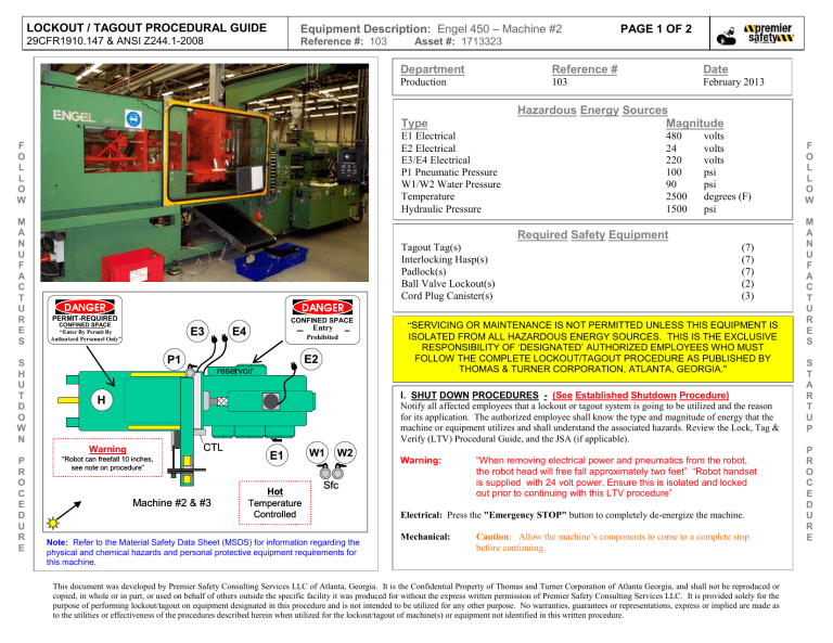
LOCKOUT / TAGOUT PROCEDURAL GUIDE Equipment Description: Engel 450 – Machine #2 29CFR1910.147 & ANSI Z244.1-2008 Reference #: 103 Asset #: 1713323 Department Reference # Production M A N U F A C T U R E S E1 Electrical E2 Electrical E3/E4 Electrical P1 Pneumatic Pressure W1/W2 Water Pressure Temperature Hydraulic Pressure S H U T D O W N P R O C E D U R E Tagout Tag(s) Interlocking Hasp(s) Padlock(s) Ball Valve Lockout(s) Cord Plug Canister(s) PERMIT-REQUIRED CONFINED SPACE “Enter By Permit By Authorized Personnel Only” E3 P1 CONFINED SPACE Entry E4 Prohibited E2 reservoir Warning CTL Machine #2 & #3 February 2013 Hazardous Energy Sources Magnitude 480 24 220 100 90 2500 1500 Required Safety Equipment volts volts volts psi psi degrees (F) psi (7) (7) (7) (2) (3) “SERVICING OR MAINTENANCE IS NOT PERMITTED UNLESS THIS EQUIPMENT IS ISOLATED FROM ALL HAZARDOUS ENERGY SOURCES. THIS IS THE EXCLUSIVE RESPONSIBILITY OF ‘DESIGNATED’ AUTHORIZED EMPLOYEES WHO MUST FOLLOW THE COMPLETE LOCKOUT/TAGOUT PROCEDURE AS PUBLISHED BY THOMAS & TURNER CORPORATION, ATLANTA, GEORGIA." I. SHUT DOWN PROCEDURES - (See Established Shutdown Procedure) Notify all affected employees that a lockout or tagout system is going to be utilized and the reason for its application. The authorized employee shall know the type and magnitude of energy that the machine or equipment utilizes and shall understand the associated hazards. Review the Lock, Tag & Verify (LTV) Procedural Guide, and the JSA (if applicable). H “Robot can freefall 10 inches, see note on procedure” Date 103 Type F O L L O W PAGE 1 OF 2 E1 Hot Temperature Controlled W1 W2 Warning: Sfc Note: Refer to the Material Safety Data Sheet (MSDS) for information regarding the physical and chemical hazards and personal protective equipment requirements for this machine. “When removing electrical power and pneumatics from the robot, the robot head will free fall approximately two feet” “Robot handset is supplied with 24 volt power. Ensure this is isolated and locked out prior to continuing with this LTV procedure” Electrical: Press the "Emergency STOP" button to completely de-energize the machine. Mechanical: Caution: Allow the machine’s components to come to a complete stop before continuing. This document was developed by Premier Safety Consulting Services LLC of Atlanta, Georgia. It is the Confidential Property of Thomas and Turner Corporation of Atlanta Georgia, and shall not be reproduced or copied, in whole or in part, or used on behalf of others outside the specific facility it was produced for without the express written permission of Premier Safety Consulting Services LLC. It is provided solely for the purpose of performing lockout/tagout on equipment designated in this procedure and is not intended to be utilized for any other purpose. No warranties, guarantees or representations, express or implied are made as to the utilities or effectiveness of the procedures described herein when utilized for the lockout/tagout of machine(s) or equipment not identified in this written procedure. F O L L O W M A N U F A C T U R E S S T A R T U P P R O C E D U R E Equipment Description: Engel 450 – Machine #2 F O L L O W M A N U F A C T U R E S S H U T D O W N P R O C E D U R E Reference #: 103 PAGE 2 OF 2 II. ENERGY ISOLATION PROCEDURES III. LOCKOUT/TAGOUT PROCEDURES IV. VERIFICATION PROCEDURES E1 Electrical: Located to the right front of the machine. Rotate the main service disconnect to "OFF" to isolate the electrical POWER. Lockout the main disconnect using an interlocking hasp, padlock, and tagout tag. After the main disconnect is locked out in the “OFF” position, “Try” the disconnect to ensure it cannot be moved to the “ON” position. Lockout the robot 24 volt electrical supply cord with a cord plug canister, interlocking hasp, padlock, and tagout tag. “Try” the machine start controls (e.g. by switching the "ON/OFF" switch to the “ON” or “START” position and observing that the machine does not operate) after lockout/tagout to make sure the correct isolation device has been secured and that the device is in the open or safe position. Switch the "ON/OFF" or “START” switch to the “OFF” position. “IF” electrically qualified and authorized to do so, verify isolation of the electrical service by conducting voltage checks across the service disconnect. E2 Electrical: Located to the rear of the machine in the robot compartment. Unplug the electrical service cord to isolate the electrical POWER. E3 Electrical: Located to the rear of the machine in the robot compartment. Unplug the electrical service cord to isolate the electrical POWER. Lockout the robot 220 volt electrical supply cord with a cord plug canister, interlocking hasp, padlock, and tagout tag. E4 Electrical: Located to the right side of the material loader. Unplug the electrical service cord to isolate the electrical POWER. Lockout the material loader 220 volt electrical supply cord with a cord plug canister, interlocking hasp, padlock, and tagout tag. P1 Pneumatic: Located to the rear of the machine by the robot compartment. Rotate the main air valve to the “CLOSED” position to block the air service. Lockout the air service valve using a ball valve lockout, interlocking hasp, padlock, and tagout tag. After the air service valve is locked out in the “CLOSED” position, “Try” the valve to ensure it cannot be moved to the “OPEN” position. Lockout the water service pressure and return valves using ball valve lockouts, interlocking hasps, padlocks, and tagout tags. After each water service valve is locked out in the “CLOSED” position, “Try” the valve to ensure it cannot be moved to the “OPEN” position. W1/W2 Water: Located right front of the machine & suspended from the ceiling. Rotate the water supply & return valves to the “CLOSED” position to block the water service. Temperature: Allow the heat cylinder to cool within limits. Hydraulics: Hydraulics is a self-contained system within the injection mould machine Note: Hydraulic pressure automatically bleeds down when POWER is removed. Verify isolation and dissipation of the air service by observing the air pressure gauge indicates "ZERO". Verify blockage of the water service by observing the water pressure gauge indicates "ZERO". Verify cool down of the unit by observing the temperature gauge or probe indicates a lowering of the temperature to safe levels. Verify isolation and dissipation of the hydraulic service by observing the hydraulic pressure gauge indicates "ZERO”. V. RETURNING TO SERVICE – (See Established Restart Procedure) Check the Engel 450 machine and the immediate area around the machine to ensure that nonessential items have been removed and that the machine components are operationally intact. Check the work area to ensure that all employees have been safely positioned or removed from the work area. P!: Remove the ball valve lockout, interlocking hasp, tag and padlock from the robot air service line and rotate the main air service valve to the “OPEN” position. W1/W2: Remove the ball valve lockouts, interlocking hasps, tags, and padlocks from the supply and return water line valves and rotate the valves to the "OPEN" position. E4: E3: E2: E1: Remove the padlock, interlocking hasp, tag and plug canister from the 24-volt robot electrical control cord and plug the cord into the service outlet. Remove the padlock, interlocking hasp, and plug canister from the 220-volt robot electrical control cord and plug the cord into the service outlet. Remove the padlock, interlocking hasp, and plug canister from the 220-volt material loader electrical control cord and plug the cord into the service outlet. Remove the padlock, interlocking hasp and tag from the main disconnect for machine #2 and turn the isolator to the "ON" position. Notify affected employees that the maintenance is completed and the Engel 450 machine is ready for production. F O L L O W M A N U F A C T U R E S S T A R T U P P R O C E D U R E


