Post-Distortion Linearising Technique Applied to Mixers
advertisement

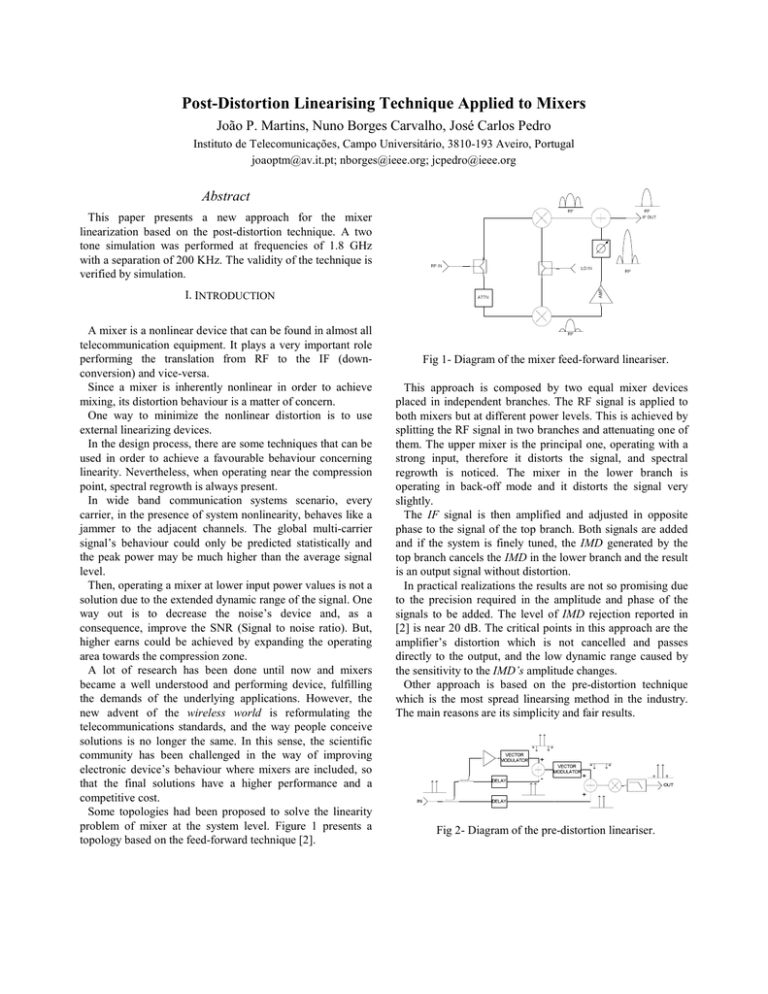
Post-Distortion Linearising Technique Applied to Mixers João P. Martins, Nuno Borges Carvalho, José Carlos Pedro Instituto de Telecomunicações, Campo Universitário, 3810-193 Aveiro, Portugal joaoptm@av.it.pt; nborges@ieee.org; jcpedro@ieee.org Abstract This paper presents a new approach for the mixer linearization based on the post-distortion technique. A two tone simulation was performed at frequencies of 1.8 GHz with a separation of 200 KHz. The validity of the technique is verified by simulation. I. INTRODUCTION A mixer is a nonlinear device that can be found in almost all telecommunication equipment. It plays a very important role performing the translation from RF to the IF (downconversion) and vice-versa. Since a mixer is inherently nonlinear in order to achieve mixing, its distortion behaviour is a matter of concern. One way to minimize the nonlinear distortion is to use external linearizing devices. In the design process, there are some techniques that can be used in order to achieve a favourable behaviour concerning linearity. Nevertheless, when operating near the compression point, spectral regrowth is always present. In wide band communication systems scenario, every carrier, in the presence of system nonlinearity, behaves like a jammer to the adjacent channels. The global multi-carrier signal’s behaviour could only be predicted statistically and the peak power may be much higher than the average signal level. Then, operating a mixer at lower input power values is not a solution due to the extended dynamic range of the signal. One way out is to decrease the noise’s device and, as a consequence, improve the SNR (Signal to noise ratio). But, higher earns could be achieved by expanding the operating area towards the compression zone. A lot of research has been done until now and mixers became a well understood and performing device, fulfilling the demands of the underlying applications. However, the new advent of the wireless world is reformulating the telecommunications standards, and the way people conceive solutions is no longer the same. In this sense, the scientific community has been challenged in the way of improving electronic device’s behaviour where mixers are included, so that the final solutions have a higher performance and a competitive cost. Some topologies had been proposed to solve the linearity problem of mixer at the system level. Figure 1 presents a topology based on the feed-forward technique [2]. Fig 1- Diagram of the mixer feed-forward lineariser. This approach is composed by two equal mixer devices placed in independent branches. The RF signal is applied to both mixers but at different power levels. This is achieved by splitting the RF signal in two branches and attenuating one of them. The upper mixer is the principal one, operating with a strong input, therefore it distorts the signal, and spectral regrowth is noticed. The mixer in the lower branch is operating in back-off mode and it distorts the signal very slightly. The IF signal is then amplified and adjusted in opposite phase to the signal of the top branch. Both signals are added and if the system is finely tuned, the IMD generated by the top branch cancels the IMD in the lower branch and the result is an output signal without distortion. In practical realizations the results are not so promising due to the precision required in the amplitude and phase of the signals to be added. The level of IMD rejection reported in [2] is near 20 dB. The critical points in this approach are the amplifier’s distortion which is not cancelled and passes directly to the output, and the low dynamic range caused by the sensitivity to the IMD’s amplitude changes. Other approach is based on the pre-distortion technique which is the most spread linearsing method in the industry. The main reasons are its simplicity and fair results. Fig 2- Diagram of the pre-distortion lineariser. Figure 2 shows the basic topology and the signal spectrum in each point of the circuit. The main idea in this point is to change the input signal in the way that the result of its conversion is a signal without distortion. So, it is necessary to characterize the mixer’s behaviour in terms of distortion. Then, before applying the signal to the mixer, it is required that it passes trough a device that has an inverse IMD characteristic in relation to the mixer. This characteristic corresponds to a gain expansion. The way to achieve such a characteristic is to subtract a nonlinear device operated at compression from other with a linear behaviour. The resultant signal has to be adjusted in phase and amplitude, with a vector modulator, Fig. 2, to match the opposite characteristic of the mixer. The results reported for the IMD cancellation in this setup are close to 15 dB [4]. The complete system’s conversion loss rate increases in relation to the single mixer due to the contribution of the pre-distorter. The main disadvantage of this setup is the deviation from the tuning point due to the aging process and changes in devices’ temperature. This is a critical point since this configuration works in open loop, so, no feedback is provided. Another setup now using a feed-back topology is presented in the Fig 3. The proposed setup presented on this paper is based on the post-distortion technique. It uses a simple circuit configuration and is a well known technique in the amplifier linearization, despite being scarcely used in this context. When applied to mixers, this technique leads to some advantages especially in the down-conversion process where the post distorter operates at low frequency and does not need any extra mixer. II. POST-DISTORTION The post-distortion technique is very similar to the predistortion. The idea beyond this method is to cascade two nonlinear blocks so that the IMD generated within the two sub-systems cancels mutually. In this approach the main block is the first followed by canceling block [5]. Fig 4- Cascade of two nonlinear blocks. The block diagram above presents a cascade of two nonlinear circuits. In order to evaluate the nonlinear distortion effects due to the iteration of the two blocks, consider the narrowband input signal: X (ω ) = S (ω ) (1) Where S( ) is the frequency domain representation of the input signal, the output of block A will be: Y1 (ω ) = G A S (ω ) + D A (ω ) Fig 3- Diagram of the frequency retranslation lineariser. This setup involves two mixing devices. One for the downconversion of the RF signal, while the other is involved in the up-conversion of the IF distorted signal back into the RF. The main branch is composed by upper mixer working in a saturated mode. Then, the IF signal has a strong IMD distortion component. This signal is sampled at the output and up-converted and subtracted from a sample of the input signal in a way that only the IMD components are preserved. This is the error signal and, after a proper shaping, it is added to the input signal. The resultant IF signal has a better IMD performance. Despite its complexity, this setup has the best IMD cancellation performance reported. The cancellation level is about 25 dB, for a phase and amplitude match of 0.1º and 0.1dB respectively. Nevertheless all these techniques are based on the use of more than one auxiliary extra mixer or are implemented in the RF part, which imposes additional design complexity. (2) DA(ω) – Distortion generated by the block A. GA – Gain of block A. This signal reaches the input of block B where he generates a signal such as: Y2 (ω ) = (GAGB )S (ω ) + GB DA (ω ) + DB (ω ) (3) Where DB( )– Distortion generated by the block B and GB – Gain of block B. The total distortion at the output is given by: Y2 D (ω ) = G B D A (ω ) + D B (ω ) (4) To cancel the distortion at the output it is required that: GB DA (ω ) = − DB (ω ) (5) In order, to eliminate the distortion at the output, the second block has to generate distortion with the same amplitude of that generated by the block A when passed through block B, but in opposite phase. One possible proposal to the post distorter is presented in the Fig 5. Fig 5- Diagram of the post distortion proposal. This setup presents two branches. From (5) it is clear that it is necessary to control two independent variables in order to achieve a proper cancellation. Those variables are the phase and the gain of the IMD. The upper branch allows to control the gain of the signal, while the lower branch is responsible for the generation and phase change of distortion. series with the flow path of the signal. But, this configuration imposes a large attenuation to the fundamental tones. The solution performed comprised an alternate path for the fundamental tones. Considering the above, the post distorter is composed by two branches. The upper one is composed by a gain path (0 dB) to reduce the attenuation caused by second block. The lower branch is composed by a series diode. An inductive reactance is used in order to vary the lower branch output signal phase. A proper bias of the Schottky diode allows for the generation of the lower branch IMD power. A resistor is inserted in series to this path in order to vary the amplitude of the lower branch signal, allowing a fine tuning of the amplitude. IV. SIMULATION VALIDATION First the mixer was characterized by simulations, Fig. 7. The values of the magnitude and phase of the mixer IMD are obtained in order to design the proper post distorter. -20 III. THEORY AND CIRCUIT DESIGN Output Power [dBm] -40 The proposed circuit is composed by two main blocks. The first block is the mixer device and generates undesired IMD distortion. The second one is the post-distorter and is required to generate IMD in opposite phase of that generated by the mixer. The nonlinear element of the post-distorter is a schottky diode. Assume the mixer is working in a zone where the phase of the IMD is in opposite phase with the fundamental tones, which is the usual case. So, the IMD generated by the diode has to be in phase in relation to the fundamental tones in order to achieve a good cancellation performance. Also, the power of the IMD generated by the diode must be the same of that generated by the mixer to allow a good cancellation performance. In order to get a fair IMD generation and the proper phase the diode has to be in -60 -80 -100 -120 -140 99 99.6 99.8 100 100.2 100.4 100.6 101 Frequency [MHz] Fig 6- Mixer output. λ/4 1:n ZSRF(ω) vRF(t) λ/4 ZSLO(ω) RF TLIN IF LO ZLIF(ω) vLO(t) 1:n λ/4 Idiode Fig 7- Full circuit showing the mixer and the post distorter. -20 V. CONCLUSIONS Output Power [dBm] -40 A new configuration for mixer linearization is proposed and validated by simulation. The simulation results are good and state this technique as an alternative to solve the mixer’s linearity issue. The post-distortion circuit presented is better than the previously linearization proposed techniques due to the very simple circuit designed at low frequencies, which allows its integration very efficiently. -60 -80 -100 -120 -140 99 99.6 99.8 100 100.2 100.4 100.6 101 ACKNOWLEDGMENTS Frequency [MHz] Fig 8- Complete system output after cancellation. The authors would like to acknowledge the financial support provided by Portuguese Science Bureau, F.C.T., under Project POCTI/ESE/37531/2002 – OPAMS. 0 Output Power [dBm] Pout REFERENCES - 50 MixerIMD -100 -150 -30 Linearized MixerIMD -25 -20 -15 -10 -5 0 Input Power [dBm] Fig 9- Sweep over RF input power from -30 dBm to 0 dBm of the mixer and the normalized complete system. For an input power of -20dBm the resulting mixer IMD optimization, is presented on Fig. 8. There a 29dB cancellation was obtained. Figure 9 presents the IMD values for input power sweep, before and after IMD cancellation. In that graph the final system was normalized to the output of the single mixer by adding an extra 5.9dB to the fundamental and 3*5.9dB to the IMD power. From there we can see that a minimum of 8 dB cancellation was obtained in all the swept power, near the compression point. All the simulations were performed with Microwave Office [7] form Applied Wave Research using the Harmonic Balance engine. [1] T. Nesimogulo, M.A. Beach, P.A. Warr and J.R. MacLeod: “Linearized mixer using frequency retranslation”. Electronic Letters, 2001, Vol.37, Nº25. [2] M. Chongcheawchamnan and I.D. Robertson: “Linearised microwave mixer using simplified feedforward technique”. Electronic Letters, 1999, Vol.35, Nº9. [3] Ellis T.J., and Rebeiz. G.M.: “ A modified feedforward technique for mixer linearisation”. IEEE Microwave Symp Dig., MTT-S, 1998, pp. 1-4. [4] Youngwook Kim, Youngsik Kim, :”Linearized Mixer Using Predistortion Technique”. IEEE Microwave and Wireless Components Letters, Vol.12, NO. 6 June 2002. [5] Kennington, Peter B. ”High-Linearity RF Amplifier Design” Norwood MA: Artech House, 2000. [6] Maas, S. A., Nonlinear Microwave Circuits, Norwood, MA: Artech House, 1988 [7] “Microwave Office 2002”; Applied Wave Research, Inc.


