III. SOLID-STATE MICROWAVE ELECTRONICS Rafuse
III. SOLID-STATE MICROWAVE ELECTRONICS
W. G. Bartholomay
A. Y. Chen
Academic and Research Staff
Prof. R. P. Rafuse
Dr. D. H. Steinbrecher
Graduate Students
V. C. Howey
R. D. V. Mohlere
D. F. Peterson
J. E. Rudzki
A. A. M. Saleh
A. 60-GHz MIXER
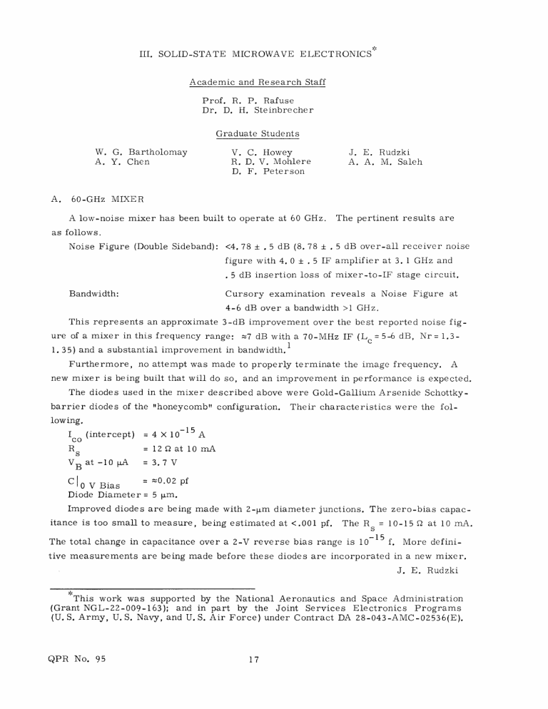
A low-noise mixer has been built to operate at 60 GHz. The pertinent results are as follows.
Noise Figure (Double Sideband): <4. 78 + . 5 dB (8. 78 . 5 dB over-all receiver noise figure with 4. 0 ± . 5 IF amplifier at 3. 1 GHz and
. 5 dB insertion loss of mixer-to-IF stage circuit.
Bandwidth: Cursory examination reveals a Noise Figure at
4-6 dB over a bandwidth >1 GHz.
This represents an approximate 3-dB improvement over the best reported noise figure of a mixer in this frequency range: z7 dB with a 70-MHz IF (Lc = 5-6 dB, Nr = 1.3-
1. 35) and a substantial improvement in bandwidth.
Furthermore, no attempt was made to properly terminate the image frequency. A new mixer is being built that will do so, and an improvement in performance is expected.
The diodes used in the mixer described above were Gold-Gallium Arsenide Schottkybarrier diodes of the "honeycomb" configuration. Their characteristics were the following.
I (intercept) = 4 X 10¹⁵ A
RS
VB at -10
= 12 0 at 10 mA
PA = 3. 7 V
C IO0 V Bias
= =0.02 pf
Diode Diameter = 5 [pm.
Improved diodes are being made with 2-pm diameter junctions. The zero-bias capacitance is too small to measure, being estimated at <.001 pf. The R = 10-15 Q at 10 mA.
s
The total change in capacitance over a 2-V reverse bias range is 10
- 1 5 f. More definitive measurements are being made before these diodes are incorporated in a new mixer.
J. E. Rudzki
This work was supported by the National Aeronautics and Space Administration
(Grant NGL-22-009-163); and in part by the Joint Services Electronics Programs
(U. S. Army, U. S. Navy, and U. S. Air Force) under Contract DA 28-043-AMC-02536(E).
QPR No. 95
(III. SOLID-STATE MICROWAVE ELECTRONICS)
References
1. D. T. Young and J. C. Irvin, "Millimeter Frequency Conversion Using Au-n-Type
GaAs Schottky Barrier Epitaxial Diodes with a Novel Contacting Technique," Proc.
IEEE (Corres.) 53, 2130 (1965).
B. SOME ASPECTS OF HIGH DYNAMIC RANGE AMPLIFICATION
Mode separation, feedback, and power dividing have been considered for distortion reduction in amplifiers whose output can be represented by a Taylor series expansion of its input. Formulas for distortion have been derived and related to compression, suppression, cross-modulation and intermodulation distortion. Reduction of distortion using both common and difference mode feedback has been demonstrated. A common-gate connected amplifier using field-effect transistors was constructed and tested to evaluate the feedback and mode separation techniques developed.
Further details may be found in the author's Master's thesis.
W. G. Bartholomay
C. INTERMODULATION DISTORTION ANALYSIS
An instrument to extend the dynamic range of standard spectrum analyzers and receivers has been designed, built, tested, and adapted for laboratory use. The test set was designed to measure odd-order intermodulation products. This difficulty of limited dynamic range in the receiver has been overcome by the test set, which effectively extends the receiver's dynamic range by reducing the amplitude of the large primary test signal by as much as 110 dB, while not affecting the smaller third-order products. The test set has been tested on a variety of receivers and been found satisfactory in operation. Third-order measurements on a variety of devices have been made which were previously impossible to make.
Further details may be found in the author's Master's thesis.
R. D. V. Mohlere
QPR No. 95
