2-CHANNEL AUTOMATIC DISTORTION METER
HIGH RELIABILITY INSTRUMENTS
2-CHANNEL AUTOMATIC DISTORTION METER
MODEL : MAK-6571W
〈
DESCRIPTION
〉
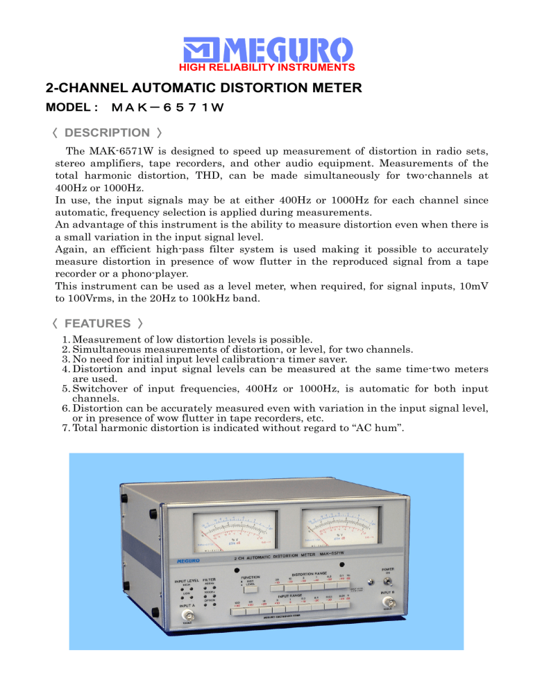
The MAK-6571W is designed to speed up measurement of distortion in radio sets, stereo amplifiers, tape recorders, and other audio equipment. Measurements of the total harmonic distortion, THD, can be made simultaneously for two-channels at
400Hz or 1000Hz.
In use, the input signals may be at either 400Hz or 1000Hz for each channel since automatic, frequency selection is applied during measurements.
An advantage of this instrument is the ability to measure distortion even when there is a small variation in the input signal level.
Again, an efficient high-pass filter system is used making it possible to accurately measure distortion in presence of wow flutter in the reproduced signal from a tape recorder or a phono-player.
This instrument can be used as a level meter, when required, for signal inputs, 10mV to 100Vrms, in the 20Hz to 100kHz band.
〈
FEATURES
〉
1.
Measurement of low distortion levels is possible.
2.
Simultaneous measurements of distortion, or level, for two channels.
3.
No need for initial input level calibration-a timer saver.
4.
Distortion and input signal levels can be measured at the same time-two meters are used.
5.
Switchover of input frequencies, 400Hz or 1000Hz, is automatic for both input channels.
6.
Distortion can be accurately measured even with variation in the input signal level, or in presence of wow flutter in tape recorders, etc.
7.
Total harmonic distortion is indicated without regard to “AC hum”.
HIGH RELIABILITY INSTRUMENTS
MODEL : MAK-6571W
〈
SPECIFICATIONS
〉
DISTORTION MEASUREMENTS (Two channels, simultaneously)
Fundamental Frequencies
(Automatic selection)
1. 400Hz ± 10% for THD
2. 1000Hz ± 10% for THD
Measuring Range
Accuracy
0.1% to 30% in six ranges
(0.1%, 0.3%, 1%, 3%, 10%, and 30% full scale.)
± 5% of full scale at each range. ( ± 10% at 0.1% range)
Fundamental Rejection Characteristics
Less 5%
Less 10%
Input Voltage
Input Impedance
3mV to 100Vrms
(0.01, 0.03, 0.1, 0.3, 1, 3, 10, 30, 100Vrms full scale)
Approx. 100k Ω ; unbalanced
Automatic Input Control Range 10dB; level monitor included
Output Terminals, TO SCOPE Output: Approx. 1Vrms at each full scale
Output Impedance: Approx. 10k Ω
LEVEL MEASUREMENTS (Two channels, simultaneously)
Frequency Range
Input Impedance
Measuring Range
Accuracy
Output Terminals, TO SCOPE
± 0.5dB: 20Hz to 50kHz (ref. 1kHz)
± 1dB: 20Hz to 100kHz (ref. 1kHz)
Approx. 100k Ω ; unbalanced
1mV to 100Vrms in nine full scale ranges
(0.01, 0.03, 0.1, 0.3, 1, 3, 10, 30, and 100Vrms full scale)
± 3% of full scale at each range (at 1000Hz)
Output: Approx. 1Vrms at each full scale
Output Impedance: Approx. 10k Ω
GENERAL DATA
Power Requirements
Dimensions, Overall
AC 100V, 115V, 215V, or 230V ± 10%, 50/60Hz; approx. 8VA
Approx. 290 (W) × 160 (H) × 290 (D) mm
Weight Approx.
Accessory, furnished Output cable 2ea
※ Specifications are subject to change without notice.
MEGURO ELECTRONICS CORPORATION
4 - 11 - 1,MINAMIKASE,SAIWAI-KU,KAWASAKI,KANAGAWA 212-0055, JAPAN
TEL : +81-44 (589) 0823 FAX : +81-44 (589) 0825
URL: http: //www.meguro.co.jp/
E-mail : mec@meguro.co.jp
(20090603)
