M90 20W LED
APPLICATION NOTE
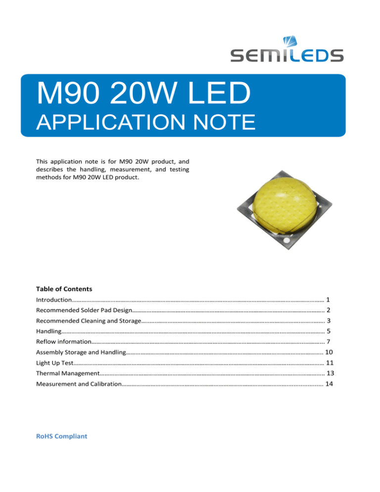
This application note is for M90 20W product, and
describes the handling, measurement, and testing
methods for M90 20W LED product.
Table of Contents
Introduction……………………………….……………………………………………..………………………………………………………… 1
Recommended Solder Pad Design……………………………………………………………………………………………………….. 2
Recommended Cleaning and Storage…..…..…………………………………………………………………………….……..……. 3
Handling……………………………………………………………………………………………………………………….……………………… 5
Reflow information…………………………………………………………………………………………………………………...………... 7
Assembly Storage and Handling………………………………………………………………………………………………………….. 10
Light Up Test……………………………………………………………………………………………………………………..………………… 11
Thermal Management…………………………………………………………………………………………………..…………………….. 13
Measurement and Calibration…………………………………………………………………………………………..................... 14
Driving methods..........................................................................................................…. 6
Thermal management .................................................................................................... 10
Packing ............................................................................................................................ 1
RoHS Compliant
M90 20W LED Application Note
Introduction
There are 3 pads for M90 20W LED which are shown in Figure 1. N & P Pads are on the left-hand side and
the right-hand side respectively, and the center is the thermal pad for heat conduction only.
Cathode Side
Pad
Function
1
Cathode
2
Anode
3
Thermal
Figure 1. M90 20W LED Pads
Notes:
1. All dimensions are in millimeters.
2. Drawings not to scale.
3. General tolerances are ±0.13 mm unless otherwise indicated.
4. Please identify the proper P/N pad positions carefully before SMT.
RoHS Compliant
M90 20W LED Application Note V1.0
Subject to change without notice
© 2005-2013 SemiLEDs. All Right Reserved
www.semileds.com
Page
1
M90 20W LED Application Note
Recommended Solder Pad Design:
Recommended Soldering Pad Design (Unit: mm) :
Recommended Stencil Pattern Design (Marked area is the opening) (Unit: mm) :
Figure 2. M90 20W recommended solder pad and stencil pad layouts
RoHS Compliant
M90 20W LED Application Note V1.0
Subject to change without notice
© 2005-2013 SemiLEDs. All Right Reserved
www.semileds.com
Page
2
M90 20W LED Application Note
Recommended Cleaning and Storage
M90 20W LED Cleaning
M90 20W LEDs are 100% cleaned before shipping. So in normal use they do not need to be cleaned again
before SMT. In the case where a minimal amount of dirt and dust particles are present during shipping &
use, a suitable cleaning solution can be applied to the lens surface.
1. During handling, keep the environment clean.
2. Gently swab the lens using a lint-free swab.
3. If needed, use a lint-free swab and Ethanol to gently remove dirt from the lens surface. Do not
use other solvents as they may directly react with the LED lens.
4. Do not use ultrasonic cleaning since this may damage to the LED.
5. Do not press or apply pressure on the lens.
Recommended Conformal Coatings
SemiLEDs has tested the following conformal coatings to be safe to use with M90 20W LED products.
Conformal coating should not be applied directly to or over the LED emitting area as it may hinder the LED’s
optical performance and reliability.
• Dow Corning 3140
• Dow Corning 3-1953
• SIL-More
SCE 3990
Harmful chemicals
SemiLEDs has determined the following chemicals to be harmful to M90 20W LEDs. The fumes from even
small amounts of these chemicals may damage the LEDs. Figure 3 shows the color shift after solvent
penetrating into the lens. Sometimes, the phenomena will recover after baking the LED for a while as in
Figure 4.
Figure 3. The color shift when solvent inside
RoHS Compliant
M90 20W LED Application Note V1.0
Subject to change without notice
© 2005-2013 SemiLEDs. All Right Reserved
www.semileds.com
Page
3
M90 20W LED Application Note
Figure 4. Recovery after baking
• Toluene, benzene, xylene
• Methyl acetate or ethyl acetate
• Cyanoacrylates
• Glycol ethers
• Isopropyl alcohol (IPA)
• Formaldehyde or butadiene
• Dymax 984-LVUF conformal coating
• Loctite Sumo Glue
• Gorilla Glue
• Clorox Clean-Up Cleaner spray
• Clorox bleach
• Loctite 384 adhesive
• Loctite 242 threadlocker
• Loctite 7387 activator
Above chemicals will affect M90 20W LED characteristics. Please do not use.
M90 20W LED Storage
Please store M90 20W LED in a dry box. The recommended storage conditions are 5~30°C and RH < 50%.
After opening the package:
1. The LEDs should be soldered within one day.
2. If unused LEDs remain, they should be stored in moisture proof packages or in a dry box. The
storage conditions are 5~30°C and RH < 50%.
3. If unused LEDs are stored for more than one week, baking treatment should be performed with the
following baking conditions; bake more than 4 hours at 60 ± 5°C.
RoHS Compliant
M90 20W LED Application Note V1.0
Subject to change without notice
© 2005-2013 SemiLEDs. All Right Reserved
www.semileds.com
Page
4
M90 20W LED Application Note
Handling
Recommended Handling
1. M90 20W emitter is a SMT type device, and it is strongly recommended that automated pick and place
machines are used to mount the LED onto the PCB. The material of pickup head should be plastic or
silicone to avoid damage to the emitters during pick and place. Please refer to Figure 5 for
recommended pickup head dimensions
Unit : mm
Figure 5. Recommended pickup tooling dimensions
2. If manual pick and place is to be applied, only plastic tweezers should used. Do not touch the lens with
the tweezers or fingers. Use tweezers to grab the M90 20W Emitters at the base gently and put onto
the PCB with solder paste carefully, as in Figure 6.
o
0
Figure 6. Proper use of tweezers
RoHS Compliant
M90 20W LED Application Note V1.0
Subject to change without notice
© 2005-2013 SemiLEDs. All Right Reserved
www.semileds.com
x
0
Page
5
M90 20W LED Application Note
If metal tweezers have to be used, do not use the one shown in Figure 7.
Tweezers
o
0
Figure 7. Proper selection of tweezers
x
0
3. M90 20W LEDs are designed to be reflow- soldered to a board. Reflow soldering should be done by a
reflow oven. Normally, use of hotplate is not recommended. The reflow soldering profile is listed on
M90 20W LED datasheet (If hot plate is used, follow the conditions; Temperature<250°C; and Time<15
seconds for each LED)
4. Do not use wave soldering or soldering-iron.
5. Incorrect handling methods during assembly are shown in Figure 8.
Pressure on the lens
x
x
0 x 0
0
Pick up from the lens
The screw driver strikes the LED
Figure 8. Incorrect handling during assembly
RoHS Compliant
M90 20W LED Application Note V1.0
Subject to change without notice
© 2005-2013 SemiLEDs. All Right Reserved
www.semileds.com
Page
6
M90 20W LED Application Note
Reflow Information
The LEDs can be soldered using the parameters listed below. As a general guideline, the users are
suggested to follow the recommended soldering profile provided by the manufacturer of the solder paste.
Although the recommended soldering conditions are specified in the list, reflow soldering at the lowest
possible temperature is preferred for the LEDs.
Notes: After the reflow process, the LED lens surface may be polluted by flux or other contamination which
RoHS Compliant
M90 20W LED Application Note V1.0
Subject to change without notice
© 2005-2013 SemiLEDs. All Right Reserved
www.semileds.com
Page
7
M90 20W LED Application Note
may impact the LED optical performance. It is suggested to clean the lens surface by Ethanol. Please refer
to Page 3, “M90 20W LED Cleaning”.
Soldering Notes
a. Solder Methods: M90 20W LEDs are designed to be soldered onto a PCB. Users could solder M90 20W
LED on the PCB by a reflow oven or a hotplate (examples shown in Figure 9) and following the reflow
soldering profile listed on the reflow information.
Do not hand solder or wave solder M90 20W LEDs. Hand or ware soldering can damage the M90 20W
LEDs.
o
o
Figure 9.
b. Solder Paste Type
SemiLEDs recommends the following solder paste compositions: SnAgCu
c. Solder Stencil Thickness
x
0
A solder stencil printer is recommended for the most consistent results. SemiLEDs recommends solder
stencil thickness of 125μm.
RoHS Compliant
M90 20W LED Application Note V1.0
Subject to change without notice
© 2005-2013 SemiLEDs. All Right Reserved
www.semileds.com
Page
8
M90 20W LED Application Note
Recommended Manual Rework Procedure
Step 1: Set up the hot plate temperature properly. Do not put the PCB on the hot plate before the
temperature is stable at the set value.
Step 2: Use tweezers to take the M90 20W LED from the PCB carefully once the solder paste has melted.
Step 3: Check the solder pad condition. Make sure the solder pads are covered by the solder paste.
Step 4: Put the LED back to the PCB properly. The time from step 2 to step 4 should be completed
within 30 seconds.
Step 5: Take the PCB out of the hot plate and put it on a heat sink to cool down the PCB temperature.
Notes:
1. Avoid solder balls which may short anode, cathode or thermal pad, such as in Figure 10.
2. Avoid any external mechanical force applied on the LED lens or substrate.
3. Do not touch the lens surface with sharp objects or fingers.
4. Leakage path may exist when the sub-mount cracks or chips due to damage from unsuitable handling.
5. Final inspection and test is suggested after the SMT process for each emitter.
Figure 10. Soldering Problem
RoHS Compliant
M90 20W LED Application Note V1.0
Subject to change without notice
x
0
© 2005-2013 SemiLEDs. All Right Reserved
www.semileds.com
Page
9
M90 20W LED Application Note
Assembly Storage and Handling
Recommendations
Do not stack PCBs or assemblies containing M90 20W emitters. The M90 20W emitter may be damaged
during stacking. The PCB should be stacked in a way to allow enough spacing above the LED lens as in
Figure 11.
o
o
Figure 11. Correct Storage Method
Incorrect Method
PCBs with M90 20W Emitters should not be stacked on top of each other, as shown in Figure 12.
x
Figure 12. Incorrect stacking of PCBs with M90 20W Emitter.
RoHS Compliant
M90 20W LED Application Note V1.0
Subject to change without notice
© 2005-2013 SemiLEDs. All Right Reserved
www.semileds.com
Page
10
M90 20W LED Application Note
Light Up Test
1. The voltage should be limited when using a power supply to light up the LEDs after SMT. The voltage
should not exceed 28V for each LED. When the voltage is above 28V, the current will be in
excess of 150mA for each chip. This may damage the emitter due to wire or pad burn out as in Figure
13. SemiLEDs recommends using constant current for light up test.
Figure 13. Bonding pad and Gold Wire burn out
2. If using a constant current limited voltage driver to light up the LEDs, please connect the power supply
and the LED module before plugging the power supply into the AC power cord. This can reduce the
probability of surge current damaging the LEDs.
3. Brightness and forward voltage are related to driving current as shown in Figure 14 ~ 15.
RoHS Compliant
M90 20W LED Application Note V1.0
Subject to change without notice
© 2005-2013 SemiLEDs. All Right Reserved
www.semileds.com
Page
11
M90 20W LED Application Note
Figure 14. M90 20W LED L‐I curve
Figure 15. M90 20W LED I-V curve
RoHS Compliant
M90 20W LED Application Note V1.0
Subject to change without notice
© 2005-2013 SemiLEDs. All Right Reserved
www.semileds.com
Page
12
M90 20W LED Application Note
Thermal Management
Figure 16. M90 20W LED thermal resistance and heat transfer structure
Thermal resistance
Figure 16 shows a cross-section and a simple thermal model for a M90 20W LED soldered on a MCPCB. A
simple thermal model or thermal circuit can illustrate the heat flowing through the MCPCB. Heat release
path from the LED chip junction to ambient is as below:
LED chip Die-attach resin ceramic MCPCB Ambient
Where:
Tj is the temperature at the junction of the device
Tc is the temperature at the Ceramic
Tb is the temperature at the point of MCPCB
Ta is the ambient air temperature
Rjc is the thermal resistance from junction to case of the Ceramic
Rcb is the thermal resistance between the case of the Ceramic and the MCPCB
Rba is thermal resistance between MCPCB and ambient
Unit of thermal resistance is ℃/W, For example, 1.5℃/W means that temperature goes up 1.5℃ per every
input power 1W.Equation 1 below represents the relationship between Tj and Ta.
Tj = Ta + Rba × Pd + Rcb × Pd + Rjc × Pd
= Tb + Rcb × Pd + Rjc × Pd
= Tc + Rjc × Pd
(Equation 1)
RoHS Compliant
M90 20W LED Application Note V1.0
Subject to change without notice
© 2005-2013 SemiLEDs. All Right Reserved
www.semileds.com
Page
13
M90 20W LED Application Note
In real life use, Tj is hard to measure directly. Tj can be calculated by measuring Tb or Ta. Then the equation
1 can be simplified to equation 2
Tj=Ta+Rja×Pd or Tj=Tb+Rjb×Pd
(Equation 2)
When heat gathers inside the LED, it causes degradation of luminous efficiency and life, and results in
degradation of expected performance. It’s essential to have a good thermal design to release the heat to
the ambient.
Measurement and Calibration
Integration Time
A long integration time will induce thermal effects in LED measurements. For example, for an integration
time of 1 sec, the LED junction temperature (Tj) may reach over 50°C, which will result in the light output
decreasing by more than 5%. It is recommended that the integration time is kept shorter than 25ms in high
power LED measurement.
Recommended Method
1. Use measurement instruments which follow CIE 127 standards. The integration time should be
shorter than 15ms.
2. If the operator uses a non‐standard tester, then calibrate the tester with a known “golden” sample
before the measurement. The golden sample should be measured by the instrument following CIE
127 standards (ea. IS CAS 140B).
RoHS Compliant
M90 20W LED Application Note V1.0
Subject to change without notice
© 2005-2013 SemiLEDs. All Right Reserved
www.semileds.com
Page
14
M90 20W LED Application Note
About Us
SemiLEDs develops and manufactures LED chips and LED components primarily for general lighting
applications, including street lights and commercial, industrial and residential lighting, along with
specialty industrial applications such as ultraviolet (UV) curing, medical/cosmetic, counterfeit
detection, and horticulture. SemiLEDs is fully ISO 9001:2008 Certified.
SemiLEDs is a publicly traded company on NASDAQ Global Select Market (stock symbol “LEDS”).
For investor information, please contact us at investors@semileds.com.
For further company or product information, please visit us at www.semileds.com or please
contact sales@ semileds.com.
www.semileds.com
ASIA PACIFIC
3F, No. 11, KeJung Rd.
Chu-Nan Site
Hsinchu Science Park
Chu-Nan 350, Miao-Li County
Taiwan, ROC
Tel: +886-37-586788
Fax: +886-37-582688
sales@semileds.com
RoHS Compliant
M90 20W LED Application Note V1.0
Subject to change without notice
© 2005-2013 SemiLEDs. All Right Reserved
www.semileds.com
Page
15


