NorthStar Battery (NSB) Telecom Application Manual
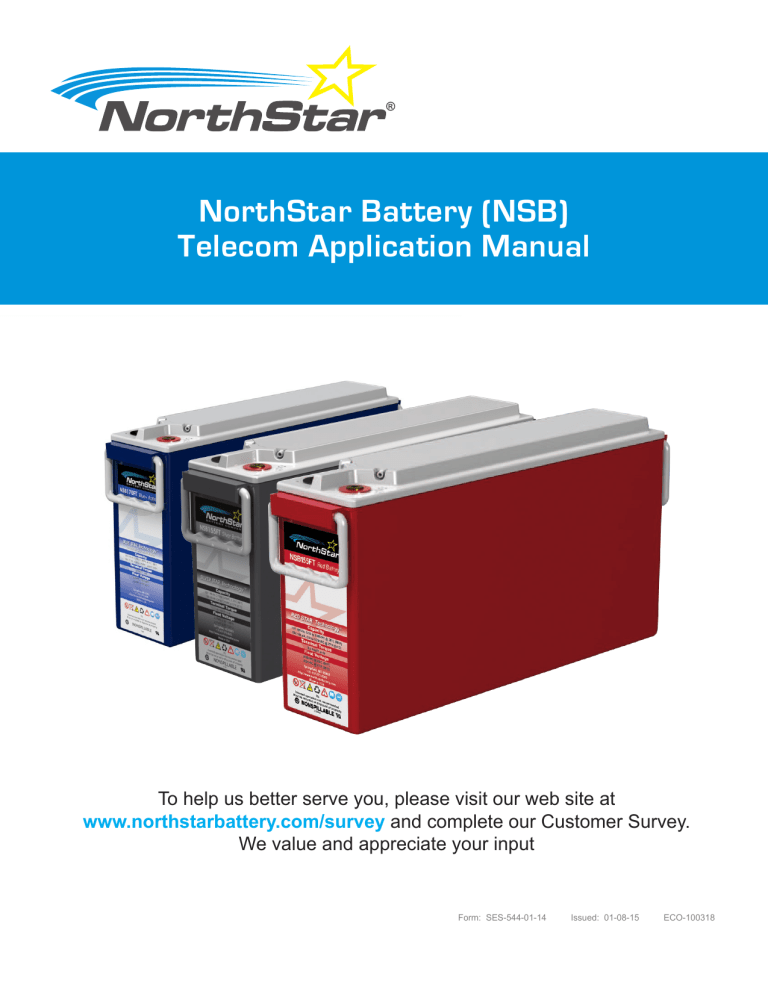
NorthStar Battery (NSB)
Telecom Application Manual
To help us better serve you, please visit our web site at www.northstarbattery.com/survey and complete our Customer Survey.
We value and appreciate your input
Form: SES-544-01-14 Issued: 01-08-15 ECO-100318
Table of Contents
5.4
5.5
6
6.1
5
5.1
5.2
5.3
6.2
6.3
6.4
6.5
3.3
4
4.1
4.2
4.3
2.4
3
3.1
3.2
2
2.1
2.2
2.3
1.1
1.2
0
1
Silver Star Technology
®
Definitions
Introduction
The Silver Star Technology ® and Semi-Stable Mains
Discharge Rate
Charge
Determining State of Charge (SOC)
Thermal Compensation
Fast Charging
Recharge Power
Discharge
Storage and Self-Discharge
End of Discharge Voltage (EODV)
Cold Temperature Performance
Useful Life
Shelf Life
Float Life vs. Temperature
Cycle Life vs. Depth of Discharge
Blue Star Technology
®
Introduction
Unstable Mains
Uncontrolled Partial State of Charge (uPSOC) Cycling uPSOC Cycling: Blue Star Technology ® vs. Standard AGM
PSOC Window vs. Useful Life
Discharge Rate
Charge
Determining State of Charge (SOC)
Thermal Compensation
Fast Charging
Recharge Power
Recharge Time
10
10
10
9
9
9
10
8
9
8
8
8
8
7
7
7
7
6
6
6
6
5
6
5
5
4
4
4
4
4
4
Form: SES-544-01-14 Issued: 01-08-15 ECO-100318
9
10
10.1
11
11.1
12
12.1
8
8.1
8.2
8.3
7
7.1
7.2
7.3
15
15.1
15.2
15.3
16
16.1
16.2
17
18
13
13.1
14
14.1
14.2
14.3
14.4
14.5
Discharge
Storage and Self-Discharge
End of Discharge Voltage (EODV)
Cold Temperature Performance
Useful Life
Shelf Life
Float Life vs. Temperature
Cycle Life vs. Depth of Discharge
BLUE+
Introduction
Charge
Determining State of Charge (SOC)
Discharge
Storage and Self-Discharge
Useful Life
Cycle Life vs. Depth of Discharge
RED STAR TECHNOLOGY
®
Introduction
The Red Star Technology ® for Float Applications
Charge
Charging Rate
Determining State of Charge (SOC)
Thermal Compensation
Fast Charging
Recharge Power
Discharge
Storage and Self Discharge
End of Discharge Voltage (EODV)
Cold Temperature Performance
Useful Life
Shelf Life
Float Life vs. Temperature
Technical Specifications
Contact
17
18
18
18
17
17
17
17
19
19
16
16
16
17
15
15
15
15
13
13
14
14
13
13
13
13
11
11
11
11
10
10
11
11
Form: SES-544-01-14 Issued: 01-08-15 ECO-100318
SILVER STAR TECHNOLOGY
®
Definitions
The definition for each of the following terms or abbre viations describes the context employed throughout this document.
Monobloc* A discrete unit of one (1) or more
2-V cells
Battery* A unit or module consisting of one
(1) or more monoblocs
VPC Volts per cell
Electrolyte Sulfuric acid diluted with de
ionized water and mixed with
sodium sulfate
* Terms may be used interchangeably given the circumstance.
1 - Introduction
1.1 The Silver Star Technology ®
Semi-Stable Mains and
Silver Star Technology ® batteries are designed to operate in applications where the mains AC is stable or semi-stable, i.e., where interruptions to power occur less than 10 hours per week. The batteries have been formulated with a unique combination of grid alloy and active materials that allows the technology to be fully recharged quickly at normal float voltages. Furthermore, outages are relatively rare. This means that the batteries can be fully recharged following an outage, which is important for maximizing cyclic performance.
The Silver Star Technology ® has also been designed to provide a high energy density. Not only does this allow for maximum backup times, but it also minimizes the monobloc footprint and reduces floor loadings. Finally, the high compression design and advanced active material formulations provide class-leading cycle life under stable or semi-stable mains conditions.
1.2 Discharge Rate
In this document, the charge and discharge rates
(amps) are expressed as multiples of I 10, where I 10 is the current for a 10-hour discharge to 100% depth-ofdischarge (DOD). These values serve to normalize data across a range of monobloc sizes. Consider the following example:
10-h discharge capacity NSB 100FT = 100 Ah (EODV =
1.80 VPC @ 25°C).
1 x I 10 = 1 x (10-h discharge current)
1 x I 10(NSB 100FT) = 1 x 10A = 10 A
2 x I 10(NSB 100FT) = 2 x 10A = 20 A
2 - Charge
In order to maximize the life of the Silver Star
Technology ® , it is recommended that the monobloc be fully recharged following an outage.
www.northstarbattery.com
Form: SES-544-01-14 Issued: 01-08-15 ECO-100318 4
2.1 Determining State of Charge (SOC)
The SOC of a monobloc can be determined by measuring the open-circuit-voltage (OCV) of the monobloc. If the monobloc has been recently recharged, a rest period of at least 3 hours after completion of recharge is required before taking measurements. The relationship between
OCV and SOC for the Silver Star Technology ® displayed in the following graph:
is
2.3 Fast Charging
If the charging system is properly sized, a fast charging regime will serve to minimize the time needed to recharge
Silver Star Technology ® batteries. This can be beneficial, for maximizing the cycle life of the product.
In a fast charging regime, the charging system is assumed to be adequately sized to provide the power needed (see Section 2.4). Charge voltage is increased which results in increased charge current. This in turn causes a discharged monobloc bank to fully recharge in a shorter time.
The increased voltage setting is known as boost voltage.
In a fast charging regime the boost voltage shall be 2.41
VPC provided that the temperature is a nominal +25°C
(+77°F). The following graph shows the recommended charging profile following a 100% DOD cycle:
A fully charged Silver Star Technology ® battery Open
Circuit Voltage will measure approximately 13.0 V.
2.2 Thermal Compensation
The optimum level for float charging the Silver Star
Technology ® is 2.27 VPC at +25°C (+77°F). If the monobloc temperature increases above this level, a thermal compensation of -4 mV/cell/°C is required for safe operation and achieving optimal life. Conversely, if the temperature decreases below 25°C, the voltage should be increased by 4 mV/cell/°C. Most modern charge rectifiers have integrated temperature monitoring and voltage regulation which should be used in any environment where temperature is not precisely controlled. The graph below shows values for an individual cell.
The table above shows the time needed to recharge following a 100% DOD cycle, depending on the maximum charge current available. If the DOD is less than
100%, the total recharge time will be less. To prevent overcharge, the duration from T1 to T2 (i.e. the time at
2.41 VPC) should always be limited to 4 hours, and then the rectifier voltage returned to the recommended float voltage.
If the monobloc temperature increases above +25°C
(+77°F), a thermal compensation of -4 mV/cell/°C to boost voltage is recommended. Conversely, if the temperature decreases below www.northstarbattery.com
Form: SES-544-01-14 Issued: 01-08-15 ECO-100318 5
25°C, the boost voltage should be increased by 4 mV/ cell/°C. The graph below shows values for an individual cell:
Maximum tolerance of 0.02 VPC
Nominal
Minimum tolerance of 0.02 VPC times in order to avoid irreversible capacity loss. The rate of self-discharge increases with increasing temperature.
For example, a monobloc at 25°C will drop from 90% to 60% in 15 months, whereas the same monobloc at
40 °C will take just 6 months. As a result, maintenance charging needs to be performed more frequently at higher temperatures.
2.4 Recharge Power
Depending on the charging system, recharge times can vary greatly following an outage. If the recharge power is relatively low, it will take longer to fully recharge a monobloc. It is recommended to provide a regular overcharge factor of between 103% and 106% SOC after a discharge.
The following chart shows the time required to fully recharge an NSB Silver Star Technology™ battery from a complete 100% DOD discharge, as a function of rectifier voltage and available current.
3 - Discharge
3.1 Storage and Self-Discharge
During storage, lead-acid monoblocs will gradually selfdischarge. It is recommended that monobloc SOC be maintained above 50% at all
3.2 End of Discharge Voltage (EODV)
In the event of a deep discharge, a recommended minimum end-of-discharge voltage (EODV) should be used to avoid over discharge. A value of 1.80 VPC is common, but this value should be adjusted based on the discharge rate. The following table provides a guide for
EODVs at various discharge rates.
Discharge Rate (Hours)
20
10
5
1
EODV (VPC)
1.85
1.80
1.75
1.70
EODV can be controlled using a Low Voltage Disconnect
(LVD) as part of the load circuit.
3.3 Cold Temperature Performance
Colder temperatures can prolong monobloc life because corrosion processes within the positive plates of the monobloc slow down as the temperature decreases.
Unfortunately, lower temperatures also lower the capacity of lead-acid monoblocs. As monobloc temperature drops below the recommended operating www.northstarbattery.com
Form: SES-544-01-14 Issued: 01-08-15 ECO-100318 6
temperature of +25° C (+77°F), the monobloc capacity decreases according to the following chart:
4 - Useful Life
4.1 Shelf Life
NSB Silver Star Technology ® batteries may be stored for up to 2 years, provided that the SOC is maintained above 50%. Failure to provide the required maintenance charging (see Section 3.1) may lead to irreversible capacity loss.
4.2 Float Life vs. Temperature
Lead-acid monoblocs operating under float in semistable mains applications are being charged most of the time. As a result, the lead grids within the positive plates undergo slow corrosion, which is a normal aging mechanism under float duty. The rate of this process increases with increasing temperature and, as a result, the temperature of monoblocs has a large affect on their float life. For each increase of 10°C, float life will decrease by a half. For example, if the temperature rises from the recommended operating temperature of +25°C, to +45°C, the expected life of the monobloc will decrease from 10 to 2.5 years (see chart below).
Under float duty, a monobloc is considered to have reached its end of life (EOL) when it can no longer deliver
80% of its original rated capacity. For example, a 100 Ah monobloc has reached EOL when its discharge capacity has dropped below 80 Ah. The relationship between capacity loss during float duty and monobloc temperature is shown in the following chart.
4.3 Cycle Life vs. Depth of Discharge
One factor which influences the cycle life of a monobloc is the depth-of-discharge (DOD). DOD is expressed as a percentage of rated capacity delivered during discharge.
For example, if a 100 Ah battery delivers 10 Ah, the DOD would be 10%. As the DOD per cycle increases, the cycle life of the monobloc will decrease. The following chart can be used to estimate the cycle life of a Silver
Star Technology ® battery if the DOD per cycle is known.
www.northstarbattery.com
Form: SES-544-01-14 Issued: 01-08-15 ECO-100318
7
BLUE STAR TECHNOLOGY
®
5 - Introduction
Blue Star Technology ® batteries (Blue batteries) are designed to operate in regions with unstable mains.
5.1 Unstable Mains
If the main AC power is routinely unavailable, it can be considered unstable. Outages can last for a few seconds or for many hours, the length and frequency of the outage limits the recharge time for the monobloc. In these applications, the monoblocs frequently cycle in an undercharged state.
During these outages, depending on monobloc size, the monobloc may never be fully discharged. Furthermore, even if power is restored, it may not be available long enough to return the monoblocs to 100% State of Charge
(SOC). This situation is known as uncontrolled Partial
State of Charge (uPSOC) cycling.
5.2 Uncontrolled Partial State of Charge (uPSOC)
Cycling
In a uPSOC cycle, the monobloc is partially discharged but may only experience a full recharge when the conditions allow, which may be very infrequent. The following chart shows data collected from the field in an unstable mains application:
As may be seen from the above chart the monobloc operates between ~90% to ~50% SOC for the first 4-days and only receives a full charge on the 5th day.
5.3 uPSOC Cycling: Blue Star Technology ®
vs. Standard AGM
The main advantage of Blue batteries is their ability to operate under uPSOC conditions without having to be fully recharged every cycle. Blue batteries have a modified electrochemistry allowing them the ability to repeatedly operate at a low SOC. Consequently the Blue batteries can be expected to perform many more uPSOC cycles than a standard AGM monobloc.
The following figure provides a comparison of cyclic performance of Blue Star Technology™ batteries compared to standard AGM www.northstarbattery.com
Form: SES-544-01-14 Issued: 01-08-15 ECO-100318
8
technology. Both technologies were cycled in a controlled lab test designed to simulate an unstable mains condition.
Clearly the Blue product is far better suited to these arduous conditions than the standard AGM, returning 6 times the cycle life.
5.4 PSOC Window vs. Useful Life
One method of estimating monobloc life in a uPSOC application is to consider the average PSOC window. The
PSOC window is defined as the difference in SOC from the recharged to the discharged state. For example, in a PSOC cycle the monobloc may be recharged to 90%
SOC and subsequently discharged to 60% SOC. The
PSOC window is therefore 30%.
Unfortunately in a real uPSOC application it is difficult to estimate the PSOC window or even the frequency of outages, but a simplistic estimation may be gained by analysis of the AC grid stability.
If the PSOC window and the average number of PSOC cycles per day are known, the monobloc life may be estimated from the following figure. For example, if the monobloc is sized to deliver 20% PSOC window per cycle and it experiences 3 cycles per day then an estimated 3 years life may be anticipated.
5.5 Discharge Rate
In this document, the charge and discharge rates
(amps) are expressed as multiples of I 10, where I 10 is the current for a 10-hour discharge to 100% depth-ofdischarge (DOD). These values serve to normalize data across a range of monobloc sizes. Consider the following example:
10-h discharge capacity NSB 170 Blue = 141Ah
(EODV = 1.8VPC @ 25°C)
1x I 10 = 1 x (10hr discharge current)
1x I 10(NSB 170 Blue) = 1 x 14.1A = 14.1A
2x I 10(NSB 170 Blue) = 2 x 14.2A = 28.2A
6 - Charge
6.1 Determining State of Charge (SOC)
The SOC of a monobloc can be determined by measuring the Open Circuit Voltage (OCV) of the monobloc. If the monobloc has been recently recharged, a rest period of at least 3 hours after completion of recharge is required before taking measurements. The relationship between
OCV and SOC for the Blue batteries is displayed in the following graph: www.northstarbattery.com
Form: SES-544-01-14 Issued: 01-08-15 ECO-100318
9
A fully charged Blue battery OCV will measure approximately 12.7 Volts.
6.2 Thermal Compensation
The optimum float charging voltage for the Blue Star
Technology ® is 2.27 VPC at +25°C (+77°F). If the monobloc temperature increases above this level, a thermal compensation of -2 mV/Cell/°C is required for safe operation and achieving optimal life. Conversely, if the temperature decreases below 25°C, the voltage should be increased by 2 mV/cell/°C. Most modern charge rectifiers have integrated temperature monitoring and voltage regulation which should be used in any environment where temperature is not precisely controlled. The graph below shows values for an individual cell.
The following chart shows the time required to fully recharge an NSB Blue battery from a complete discharge, as a function of rectifier voltage and available current.
6.3 Fast Charging
Blue batteries are designed for uPSOC under standard float conditions. However, in very unstable mains applications, if the rectifier voltage can be increased, this may help to maintain the standby autonomy by moving the uPSOC window to a higher state of charge.
6.4 Recharge Power
Depending on the charging system, recharge times can vary greatly following an outage. If the recharge power is relatively low, it will take longer to recharge a monobloc to
100% SOC from a full discharge.
6.5 Recharge Time
The recharge time can also be estimated from the following formulas:
PSOC Recharge time with 100% charge return =
Capacity * V * %DOD / Recharge Power (W)
Or
Capacity * %DOD / Current (A)
Example: 2 hour discharge on 10 hr monobloc bank
(20% DOD) with 20% to charge the monobloc (1 hour recharge).
Example: 400Ah monobloc bank with same discharge and recharged with 3.8 kW (1 hour recharge)
7 - Discharge
7.1 Storage and Self-Discharge
During storage, lead-acid monoblocs will gradually self-discharge. It is recommended that monobloc SOC be maintained above 50% at all times in order to avoid irreversible capacity loss. The rate of self-discharge increases with increasing temperature. For example, a monobloc at 25°C will drop from 90% to 60% in 15 months, whereas the same monobloc at 40 °C will take just 6 months. As a result, maintenance charging needs to be performed more frequently at higher temperatures www.northstarbattery.com
Form: SES-544-01-14 Issued: 01-08-15 ECO-100318
10
7.2 End of Discharge Voltage (EODV)
In most applications Blue batteries never go to a completely discharged state due to their uPSOC operation. However, in the event of a deep discharge, a recommended minimum EODV should be used to avoid over discharge. 1.80 VPC is common, but this value should be adjusted based on discharge rate.
Discharge Rate (Hours)
20
10
5
1
EODV (VPC)
1.85
1.80
1.75
1.70
EODV can be controlled using a Low Voltage Disconnect
(LVD) as part of the load circuit.
7.3 Cold Temperature Performance
Colder temperatures can prolong monobloc life because corrosion processes within the positive plates of the monobloc slow down as the temperature decreases.
Unfortunately, lower temperatures also lower the capacity of lead-acid monoblocs. As monobloc temperature drops below the recommended operating temperature of +25°
C (+77°F), the monobloc capacity decreases according to the following chart:
8 - Useful Life
8.1 Shelf Life
NSB Blue batteries may be stored for up to 2 years, provided that the SOC is maintained above 50%. Failure to provide the required maintenance charging (see
Section 3.1) may lead to irreversible capacity loss.
8.2 Float Life vs. Temperature
The operating temperature of monoblocs can have a large affect on their float life. For each increase of
10°C, float life will decrease by a half. For example, if the temperature rises from the recommended operating temperature of +25°C to +45°C, the expected life of the monobloc will decrease from 7 to 2 years.
www.northstarbattery.com
Form: SES-544-01-14 Issued: 01-08-15 ECO-100318
11
8.3 Cycle Life vs. Depth of Discharge
One factor which influences the cycle life of a monobloc is the depth-of-discharge (DOD). DOD is expressed as a percentage of rated capacity delivered during discharge.
For example, if a 100 Ah monobloc delivers 10 Ah, the
DOD would be 10%. As the DOD per cycle increases, the cycle life of the monobloc will decrease. The following chart can be used to estimate the cycle life of a
Blue battery if the DOD per cycle is known.
www.northstarbattery.com
Form: SES-544-01-14 Issued: 01-08-15 ECO-100318 12
BLUE+
9 - Introduction
Blue+ batteries are designed to operate in regions with unstable mains while maintaining higher volumetric energy density than standard Blue. Except as noted below, all the information contained in the “Blue Star Technology” section also applies to Blue+.
10 - Charge
10.1 Determining State of Charge (SOC)
The SOC of a monobloc can be determined by measuring the Open Circuit Voltage (OCV) of the monobloc. If the monobloc has been recently recharged, a rest period of at least 3 hours after completion of recharge is required before taking measurements. The relationship between
OCV and SOC for the Blue+ batteries is displayed in the following graph:
11 - Discharge
11.1 Storage and Self-Discharge
During storage, lead-acid monoblocs will gradually self-discharge. It is recommended that monobloc SOC be maintained above 50% at all times in order to avoid irreversible capacity loss. The rate of self-discharge increases with increasing temperature. For example, a monobloc at 25°C will drop from 90% to 60% in 15 months, whereas the same monobloc at 40 °C will take just 6 months. As a result maintenance charging needs to be performed more frequently at higher temperatures.
A fully charged Blue+ battery OCV will measure approximately 13.0 Volts.
www.northstarbattery.com
Form: SES-544-01-14 Issued: 01-08-15 ECO-100318 13
12 - Useful Life
12.1 Cycle Life vs. Depth of Discharge
Blue+ batteries are designed to be able to operate in highly cyclic applications as well as PSOC applications.
The cycle life versus DOD can be expected to be the same as mentioned for Blue batteries during standard cyclic operation. However, during optimal charging regime the Blue+ batteries can be expected to achieve cycle life according to the chart below.
100,000
Cycle life vs. DOD
NortStar optimal charging conditions
10,000
1,000
100
0% 10% 20% 30% 40%
Depth of Discharge
50% 60% 70% www.northstarbattery.com
Form: SES-544-01-14 Issued: 01-08-15 ECO-100318 14
RED STAR TECHNOLOGY
®
13 - Introduction
13.1 The Red Star Technology ®
Applications
for Float
The Red Star Technology ® batteries (Red batteries) are designed specifically for float applications where power outages are rare. The batteries have been formulated with a unique combination of grid alloy and active material, which allows the technology to resist the normal corrosion processes that occur within lead-acid monoblocs. The float life of these monoblocs is class leading.
In addition to an excellent corrosion resistance, the Red batteries have also been formulated to provide a high energy density. Not only does this allow for maximum backup times, but it also minimizes the monobloc footprint and reduces floor loadings. Finally, the Red batteries have been designed so that they can be charged quickly, so that they are always ready to provide power in the event of a mains outage.
14 - Charge
In order to maximize the life of the Red batteries, it is recommended that the monoblocs be fully recharged following an outage.
14.1 Charging Rate
In this document, the charge rates (amps) are expressed as multiples of I 10, where I 10 is the current for a 10hour discharge to 100% depth-of-discharge (DOD).
These values serve to normalize data across a range of monobloc sizes. Consider the following example:
10-h discharge capacity NSB 100FT = 100 Ah (EODV =
1.80 VPC @ 25°C).
1 x I 10 = 1 x (10-h discharge current)
1 x I 10(NSB 100FT) = 1 x 10A = 10 A
2 x I 10(NSB 100FT) = 2 x 10A = 20 A
14.2 Determining State of Charge (SOC)
The SOC of a monobloc can be determined by measuring the open-circuit-voltage (OCV) of the monobloc. If the monobloc has been recently recharged, a rest period of at least 3 hours after completion of recharge is required before taking measurements. The relationship between
OCV and SOC for the Red batteries is displayed in the following graph: www.northstarbattery.com
Form: SES-544-01-14 Issued: 01-08-15 ECO-100318 15
A fully charged Red battery OCV will measure approximately 13.0 V.
14.3 Thermal Compensation
The optimum level for float charging the Red Star
Technology ® is 2.27 VPC at +25°C (+77°F). If the monobloc temperature increases above this level, a thermal compensation of -4 mV/cell/°C is required for safe operation and achieving optimal life. Conversely, if the temperature decreases below 25°C, the voltage should be increased by 4 mV/cell/°C. Most modern charge rectifiers have integrated temperature monitoring and voltage regulation which should be used in any environment where temperature is not precisely controlled. The graph below shows values for an individual cell.
turn, causes a discharged monobloc bank to fully recharge in a shorter time.
The increased voltage setting is known as boost voltage.
In a fast charging regime the boost voltage shall be 2.41
VPC provided that the temperature is a nominal +25°C
(+77°F).
Note: Higher charging voltage will increase hydrogen evolution rates.
If the DOD is less than 100%, the total recharge time will be less. To prevent overcharge, the duration from T1 to
T2 (i.e. the time at 2.41 VPC) should always be limited to 4 hours, and then the rectifier voltage returned to the recommended float voltage.
If the monobloc temperature increases above +25°C
(+77°F), a thermal compensation of -4 mV/cell/°C to boost voltage is recommended. Conversely, if the temperature decreases below 25°C, the boost voltage should be increased by 4 mV/cell/°C. The graph below shows values for an individual cell:
Maximum tolerance of 0.02VPC
Nominal
14.4 Fast Charging
If the charging system is properly sized, a fast charging regime will serve to minimize the time needed to recharge
Red batteries.
In a fast charging regime, the charging system is assumed to be adequately sized to provide the power needed (see Section 2.5). Charge voltage is increased which maintains the charge current throughout the charging period. This, in
Minimum tolerance of 0.02VPC
14.5 Recharge Power
Depending on the charging system, recharge times can vary greatly following an outage. If the recharge power is relatively low, it will take longer to fully recharge a monobloc. Providing a regular overcharge factor between 103% and 106% after a discharge is recommended. Overcharge factor being the amount of charge put back into a monobloc after a discharge, normally approximately 105%.
The following chart shows the time required to fully recharge a NSB Red battery from a complete 100% DOD discharge, as a function of rectifier voltage and available current.
www.northstarbattery.com
Form: SES-544-01-14 Issued: 01-08-15 ECO-100318
16
15 - Discharge
15.1 Storage and Self Discharge
During storage, lead-acid monoblocs will gradually selfdischarge. It is recommended that monobloc SOC be maintained above 50% at all times in order to avoid irreversible capacity loss. The rate of self-discharge increases with increasing temperature. For example, a monobloc at 25°C will drop from 90% to 60% in 15 months, whereas the same monobloc at 40 °C will take just 6 months. As a result, maintenance charging needs to be performed more frequently at higher temperatures.
Discharge Rate (Hours)
20
10
5
1
EODV (VPC)
1.85
1.80
1.75
1.70
EODV can be controlled using a Low Voltage Disconnect
(LVD) as part of the load circuit.
15.3 Cold Temperature Performance
Colder temperatures can prolong monobloc life because corrosion processes within the positive plates of the monobloc slow down as the temperature decreases.
Unfortunately, lower temperatures also lower the capacity of lead-acid monoblocs. As monobloc temperature drops below the recommended operating temperature of +25°
C (+77°F), the monobloc capacity decreases according to the following chart:
15.2 End of Discharge Voltage (EODV)
In the event of a deep discharge, a recommended minimum end-of-discharge voltage (EODV) should be used to avoid over discharge. A value of 1.80 VPC is common, but this value should be adjusted based on the discharge rate. The following table provides a guide for
EODVs at various discharge rates.
16 - Useful Life
16.1 Shelf Life
NSB Red batteries may be stored for up to 2 years, provided that the SOC is maintained above 50%. Failure to provide the required maintenance charging (see
Section 3.1) may lead to irreversible capacity loss.
www.northstarbattery.com
Form: SES-544-01-14 Issued: 01-08-15 ECO-100318
17
16.2 Float Life vs. Temperature
Due to constant float charging, the lead grids within the positive plates undergo slow corrosion, which is a normal aging mechanism. The rate of this process increases with increasing temperature and, as a result, the temperature of monoblocs has a large affect on their float life. For example, if the temperature rises from the recommended operating temperature of +25°C, to +45°C, the expected life of the monobloc will decrease from 12 to 3 years
(see chart below). This is the overall average operating temperature during the life of the monobloc.
16.3 Cycle Life vs. Depth of Discharge
One factor which influences the cycle life of a monobloc is the depth-of-discharge (DOD). DOD is expressed as a percentage of rated capacity delivered during discharge.
For example, if a 100 Ah battery delivers 10 Ah, the DOD would be 10%. As the DOD per cycle increases, the cycle life of the monobloc will decrease. The following chart can be used to estimate the cycle life of a RED Star
Technology ® battery if the DOD per cycle is known.
Under float duty, a monobloc is considered to have reached its end of life (EOL) when it can no longer deliver
80% of its original rated capacity. For example, a 100 Ah monobloc has reached EOL when its discharge capacity has dropped below 80 Ah. The relationship between capacity loss during float duty and monobloc temperature is shown in the following chart.
www.northstarbattery.com
Form: SES-544-01-14 Issued: 01-08-15 ECO-100318
18
17 - Technical Specifications
For detailed technical specifications, please refer to the
Product Data Sheet.
18 - Contact
NorthStar Americas
NorthStar Battery Company LLC
4000 Continental Way
Springfield, MO, 65803,
United States of America info @ northstarbattery.com
Tel: +1 417 575 8200
Fax: +1 417 575 8250
NorthStar Europe
SiteTel Sweden AB
Staffans Väg 6
SE-192 07 Sollentuna,
Stockholm, Sweden europe @ northstarbattery.com
Tel: +46 8 410 102 00
Fax: +46 8 638 06 00
NorthStar Middle East, Africa
SiteTel Sweden AB JTL Branch
Office 702, Saba 1 Tower
Jumeirah Lake Towers, Dubai United Arab Emirates mea @ northstarbattery.com
Tel: +971 4 423 8060
Fax: +971 4 423 8061
NorthStar in Asia-Pacific
NS Asia Pacific Sdn. Bhd.
B2-3A-13A, Solaris Dutamas
No. 1, Jalan Dutamas 1, 50480
Kuala Lumpur, Malaysia asia@northstarbattery.com
Tel: +60 3 6419 0711 www.northstarbattery.com
Form: SES-544-01-14 Issued: 01-08-15 ECO-100318 19
![VET SYSTEM 30 [PD-88-E - Rev. 00]](http://s3.studylib.net/store/data/007203237_1-c7eac5c1840b8e1daef1da210f7c53d4-300x300.png)
