VOL. 10, NO. 7, APRIL 2015
ARPN Journal of Engineering and Applied Sciences
ISSN 1819-6608
©2006-2015 Asian Research Publishing Network (ARPN). All rights reserved.
www.arpnjournals.com
DESIGN AND IMPLEMENTATION OF MULTIPORT BIDIRECTIONAL DCDC CONVERTER FOR HYBRID ENERGY STORAGE SYSTEMS
R. B. Devi1 and S. M. Balaganesan2
1Department
of Electrical and Electronics Engineering, Power Electronics and Drives, Sri Ramakrishna Engineering College,
Coimbatore, India
2Department of Electrical and Electronics Engineering, Sri Ramakrishna Engineering College, Coimbatore, India
E-Mail: deviram92@gmail.com
ABSTRACT
Multiport dc/dc converters are widely used in hybrid energy generation systems, microgrids and electric vehicles
to provide stable power to key loads with high power density. In this project, a multiport isolated bidirectional dc–dc
converter is anticipated for hybrid energy storage system in microgrids. Microgrids are connected to the nearby renewable
energy generation systems as solar, wind, etc. These systems do not provide pure DC voltage for conversion into AC
required by the grid. Hence a single stage DC-AC-DC conversion is required. For energy management and single stage
power conversion, multiport BDC is the best choice. Also to minimize the switching losses and henceforth to improve the
efficiency of the converter system, Zero Voltage Switching (ZVS) can be achieved for all switches in any direction of
power flow in the whole load range with decoupled duty cycle control and phase shift.
Keywords: DC-bus microgrid, hybrid energy management, hybrid energy storage, multiport bidirectional converter.
INTRODUCTION
With the rapid development of electric vehicles
and distributed renewable energy power systems,
microgrid plays a major role in distributed generation.
Energy storage system is an essential part of the
microgrid. Battery is the most mature technology for
Electrical Energy Storage (EES). It possesses high energy
density [1]. On the other hand, its dynamic response is
slow which makes it unsuitable to satisfy the requirements
of sudden changes on load or power. Meanwhile, a super
capacitor has short charging/discharging time and high
power density. Therefore, the hybrid system combined
with the battery and the super capacitor can be used to
improve the performance of the energy storage system.
Battery is used for energy storage, while super capacitor is
used for transient energy storage and fast supplement.
To ensure the hybrid system to be highly
efficient, safe, reliable, the design should consider two
aspects: construction and energy management strategy.
For construction, multiport dc–dc converters are the
optimum choice particularly for systems where diverse
sources and storage elements are to be integrated.
An isolated bidirectional multiport DC-DC
converter is proposed to serve for two main purposes such
as to provide galvanic isolation between the converter
units using high voltage transformer and to prevent
voltage mismatch by providing phase shift between the
converter voltages.
DESCRIPTION OF CONVERTER TOPOLOGY
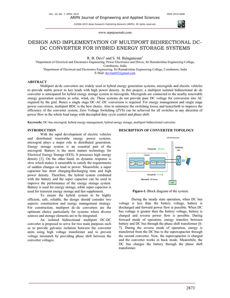
Figure-1. Block diagram of the system.
During the steady state operation, when DC bus
voltage is less than the battery voltage, battery is
discharged and forward power flow is possible. When DC
bus voltage is greater than the battery voltage, battery is
charged and reverse power flow is possible. During
forward mode of operation, energy transfers between
battery and DC bus through the phase shift transformer [67]. During the reverse mode of operation, energy is
transferred from the DC bus to the supercapacitor through
the second converter. Now, the supercapacitor is charged
and the converter works in buck mode. Meanwhile, the
DC bus charges the battery through the phase shift
transformer.
2873
VOL. 10, NO. 7, APRIL 2015
ARPN Journal of Engineering and Applied Sciences
ISSN 1819-6608
©2006-2015 Asian Research Publishing Network (ARPN). All rights reserved.
www.arpnjournals.com
Figure-2. Topology of the multiport converter.
The converter units are distributed symmetrically
on both sides of the transformer. The left side (primary
side) is defined as the battery side. On this side, inductors
L1, L2 and switches S1u, S2u, S1d, S2d (including body
diodes and parasitic capacitors) compose a two-channel
interleaving Buck/Boost construct, in which the lowvoltage port is connected to the battery. UBA is defined as
the battery voltage. The right side (secondary side) is
defined as the dc-bus side. On this side, inductors L3, L4
and switches S3u , S4u, S3d, S4d (including body diodes and
parasitic capacitors) compose a two-channel interleaving
Buck/Boost construct, in which the high-voltage port is
connected to the dc bus and the low voltage port is
connected to the super capacitor. UDC is the dc-bus voltage
and USC is the super capacitor voltage. The converter also
has an internal high-voltage port on the battery side, which
is connected to a filter capacitor Cc without any power
input or output. Performance of the converter can be
improved by controlling the voltage of this port. So, it is
also supposed that the converter is named as a “3 +
1”−port bidirectional converter.
SIMULATION RESULTS
The simulink model of multiport BDC is shown
in Figure-3. The multiport BDC is connected to the Dc bus
connecting the source and the load. A resistive load is
connected across the terminals of the DC bus.
Figure-4. Battery output.
Figure-5. DC bus output voltage.
CONCLUSIONS
The proposed multiport bidirectional dc-dc
converter, which can be named as a “3 + 1” port
bidirectional converter consists of four ports, among
which one high voltage port is connected to the dc bus,
two low voltage ports to battery and supercapacitor
respectively, and the accessional fourth port for voltage
matching control. The multiport bidirectional converter
and the hybrid energy storage control strategy can realize
proper transmission and distribution of energy. The
converter units on both sides of the transformer use
interleaving control so that the output current ripple is
small. Also, compared to the conventional multiport
topology without the fourth voltage matching port,
reactive power and circulating current are greatly reduced
in this proposed topology.
REFERENCES
[1] S. M. Lukic, J. Cao, R. C. Bansal, F. Rodriguez, and
A. Emadi, “Energy storage systems for automotive
applications,” IEEE Trans. Ind. Electron. vol. 55, no.
6, pp. 2258-2267, June 2008.
Figure-3. Multiport BDC block.
[2] H.Wu, R. Chen, J. Zhang, Y. Xing, H. Hu, and H. Ge,
“A family of three port half-bridge converters for a
stand-alone renewable power system,” IEEE Trans.
2874
VOL. 10, NO. 7, APRIL 2015
ARPN Journal of Engineering and Applied Sciences
ISSN 1819-6608
©2006-2015 Asian Research Publishing Network (ARPN). All rights reserved.
www.arpnjournals.com
Power Electron. vol. 26, no. 9, pp. 2697-2706,
September 2011.
[3] H. Xiao and S. Xie, “A ZVS bidirectional DC–DC
converter with phase shift plus PWM control scheme,”
IEEE Trans. Power Electron. vol. 23, no. 2, pp. 813823, March 2008.
[4] F. Z. Peng, H. Li, G. J. Su, and J. S. Lawler, “A new
ZVS bidirectional dc-dc converter for fuel cell and
battery application,” IEEE Trans. Power Electron. vol.
19, no. 1, pp. 54-65, January 2004.
[5] J.-S. Lai and D. J. Nelson, “Energy management
power converters in hybrid electric and fuel cell
vehicles,” in Proc. IEEE Ind. Electron., Taipei,
Taiwan, Volume 95, Issue 4, April 2007, pp. 766-777.
[6] S. Falcones, R. Ayyanar, and X. Mao, “A DC–DC
multiport-converter based solid-state transformer
integrating distributed generation and storage,” IEEE
Trans. Power Electron. vol. 28, no. 5, pp. 2192-2203,
May 2013.
[7] H. Tao, A. Kotsopoulos, J. L. Duarte, and M. A. M.
Hendrix, “Transformer-coupled multiport ZVS
bidirectional dc-dc converter with wide input range,”
IEEE Trans. Power Electron. vol. 23, no. 2, pp. 771781, March. 2008.
[8] L. Wang, Z. Wang, and H. Li, “Asymmetrical duty
cycle control and decoupled power flow design of a
three-port bidirectional DC-DC converter for fuel cell
vehicle application,” IEEE Trans. Power Electron. vol.
27, no. 2, pp. 891-904, February 2012.
[9] H. Yoo, S. K. Sul, Y. Park, and J. Jeong, “System
integration and powerflowmanagement for a series
hybrid electric vehicle using supercapacitors and
batteries,” IEEE Trans. Ind. Appl. vol. 44, no. 1, pp.
108-114, January– February 2008.
[10] J. Cao and A. Emadi, “A new battery/ultracapacitor
hybrid energy storage system for electric, hybrid, and
plug-in hybrid electric vehicles,” IEEE Trans. Power
Electron. vol. 27, no. 1, pp. 122-132, January 2012.
2875


