49 - Okonite
advertisement
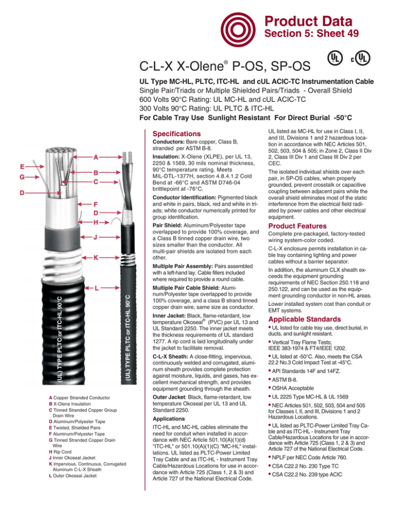
Product Data Section 5: Sheet 49 ® C-L-X X-Olene P-OS, SP-OS UL R c UL R UL Type MC-HL, PLTC, ITC-HL and cUL ACIC-TC Instrumentation Cable Single Pair/Triads or Multiple Shielded Pairs/Triads - Overall Shield 600 Volts 90°C Rating: UL MC-HL and cUL ACIC-TC 300 Volts 90°C Rating: UL PLTC & ITC-HL For Cable Tray Use Sunlight Resistant For Direct Burial -50°C Specifications Conductors: Bare copper, Class B, stranded per ASTM B-8. Insulation: X-Olene (XLPE), per UL 13, 2250 & 1569, 30 mils nominal thickness, 90°C temperature rating. Meets MIL-DTL-1377H, section 4.8.4.1.2 Cold Bend at -66°C and ASTM D746-04 brittlepoint at -76°C. Conductor Identification: Pigmented black and white in pairs, black, red and white in triads; white conductor numerically printed for group identification. Pair Shield: Aluminum/Polyester tape overlapped to provide 100% coverage, and a Class B tinned copper drain wire, two sizes smaller than the conductor. All multi-pair shields are isolated from each other. (UL) TYPE PLTC or ITC-HL 90°C (UL) TYPE PLTC or ITC-HL 90°C Multiple Pair Assembly: Pairs assembled with a left-hand lay. Cable fillers included where required to provide a round cable. A Copper Stranded Conductor B X-Olene Insulation C Tinned Stranded Copper Group Drain Wire D Aluminum/Polyester Tape E Twisted, Shielded Pairs F Aluminum/Polyester Tape G Tinned Stranded Copper Drain Wire H Rip Cord J Inner Okoseal Jacket K Impervious, Continuous, Corrugated Aluminum C-L-X Sheath L Outer Okoseal Jacket Multiple Pair Cable Shield: Aluminum/Polyester tape overlapped to provide 100% coverage, and a class B strand tinned copper drain wire, same size as conductor. Inner Jacket: Black, flame-retardant, low temperature Okoseal® (PVC) per UL 13 and UL Standard 2250. The inner jacket meets the thickness requirements of UL standard 1277. A rip cord is laid longitudinally under the jacket to facilitate removal. C-L-X Sheath: A close-fitting, impervious, continuously welded and corrugated, aluminum sheath provides complete protection against moisture, liquids, and gases, has excellent mechanical strength, and provides equipment grounding through the sheath. Outer Jacket: Black, flame-retardant, low temperature Okoseal per UL 13 and UL Standard 2250. Applications ITC-HL and MC-HL cables eliminate the need for conduit when installed in accordance with NEC Article 501.10(A)(1)(d) "ITC-HL" or 501.10(A)(1)(C) "MC-HL" installations. UL listed as PLTC-Power Limited Tray Cable and as ITC-HL - Instrument Tray Cable/Hazardous Locations for use in accordance with Article 725 (Class 1, 2 & 3) and Article 727 of the National Electrical Code. UL listed as MC-HL for use in Class I, II, and III, Divisions 1 and 2 hazardous location in accordance with NEC Articles 501, 502, 503, 504 & 505; in Zone 2, Class II Div 2, Class III Div 1 and Class III Div 2 per CEC. The isolated individual shields over each pair, in SP-OS cables, when properly grounded, prevent crosstalk or capacitive coupling between adjacent pairs while the overall shield eliminates most of the static interference from the electrical field radiated by power cables and other electrical equipment. Product Features Complete pre-packaged, factory-tested wiring system-color coded. C-L-X enclosure permits installation in cable tray containing lighting and power cables without a barrier separator. In addition, the aluminum CLX sheath exceeds the equipment grounding requirements of NEC Section 250.118 and 250.122, and can be used as the equipment grounding conductor in non-HL areas. Lower installed system cost than conduit or EMT systems. Applicable Standards • UL listed for cable tray use, direct burial, in ducts, and sunlight resistant. • Vertical Tray Flame Tests; IEEE 383-1974 & FT4/IEEE 1202. • UL listed at -50°C. Also, meets the CSA 22.2 No.3 Cold Impact Test at -45°C. • API Standards 14F and 14FZ. • ASTM B-8. • OSHA Acceptable • UL 2225 Type MC-HL & UL 1569 • NEC Articles 501, 502, 503, 504 and 505 for Classes I, II, and III, Divisions 1 and 2 Hazardous Locations. • UL listed as PLTC-Power Limited Tray Cable and as ITC-HL - Instrument Tray Cable/Hazardous Locations for use in accordance with Article 725 (Class 1, 2 & 3) and Article 727 of the National Electrical Code. • NPLF per NEC Code Article 760. • CSA C22.2 No. 230 Type TC • CSA C22.2 No. 239 type ACIC UL c UL C-L-X X-Olene P-OS, SP-OS R R UL Type MC-HL, PLTC, ITC-HL and cUL ACIC-TC Instrumentation Cable Product Data Section 5: Sheet 49 Single Pair/Triads or Multiple Shielded Pairs/Triads - Overall Shield 600 Volts 90°C Rating: UL MC-HL and cUL ACIC-TC 300 Volts 90°C Rating: UL PLTC & ITC-HL N um be ro N fP um ai be rs ro fT In n ria Th er ds ic Ja kn ck es et s N -m om O in ils .D a .I lC nc o he re s C -L -X O .D .I O nc ut he er s Ja ck N et o m O min ils .D a .- lC In a ch b l es e C ro A ss re -S a ec = ti (s o q na in l A pp ) ro (lb x s/ Ne 10 t W A pp 00’ e ) ig r ht (lb ox s/ Sh 10 ip 00 W ’) e ig ht C at al og N um be r For Cable Tray Use Sunlight Resistant For Direct Burial -50°C #16 AWG 567-75-3401 567-70-3402 567-70-3404 1 2 4 45 60 60 0.35 0.58 0.70 0.58 0.80 0.93 50 50 50 0.69 0.91 1.04 0.37 0.65 0.85 180 325 424 219 405 504 567-70-3408 567-70-3412 567-70-3424 8 12 24 80 80 80 0.92 1.10 1.44 1.19 1.37 1.78 50 50 60 1.30 1.48 1.91 1.33 1.73 2.87 650 842 1450 752 985 1640 567-70-3436 567-76-3401 567-71-3402 36 1 2 110 45 60 1.82 0.37 0.64 2.19 0.58 0.89 60 50 50 2.32 0.69 1.00 4.23 0.37 0.79 2145 195 376 2480 234 456 4 8 12 60 80 80 0.75 1.06 1.26 1.02 1.34 1.56 50 50 60 1.13 1.45 1.69 1.00 1.64 2.24 500 800 1090 580 945 1235 567-71-3404 567-71-3408 567-71-3412 #18 AWG 567-70-3302 567-70-3304 2 4 45 60 0.50 0.67 0.71 0.89 50 50 0.82 1.00 0.53 0.79 253 365 333 445 567-70-3308 567-70-3312 8 12 60 80 0.83 1.00 1.06 1.29 50 50 1.17 1.40 1.08 1.54 503 693 583 799 567-70-3324 567-70-3336 24 36 80 80 1.34 1.55 1.64 1.92 60 60 1.78 2.05 2.48 3.29 1125 1545 1290 1835 567-71-3302 567-71-3304 567-71-3308 2 4 8 60 60 80 0.62 0.73 0.98 0.84 0.97 1.24 50 50 50 0.95 1.08 1.35 0.71 0.92 1.43 326 428 658 406 508 764 567-71-3312 567-71-3324 12 24 80 80 1.15 1.58 1.47 1.96 50 60 1.58 2.09 1.96 3.42 860 1505 1003 1760 ELECTRICAL SPECIFICATIONS Conductor Resistance, nominal - ohms/1000 ft......@20°C ..........@25°C 16 AWG ................................................................4.34 .................4.43 18 AWG ................................................................6.93 .................7.07 Insulation Test Voltage (spark test) ....................................7500 Volts ac Dielectric Test Voltage .......................................................3000 Volts ac Insulation Resistance Constant @60°F minimum ...10,000 ohms-1000 ft. Loop Resistance, nominal (2 cdr.) - ohms/1000 ft .@20°C ..........@25°C 16 AWG .................................................................8.68 .................8.86 18 AWG .................................................................13.9 .................14.2 = Cross-sectional area for calculation of cable tray fill in accordance with NEC Section 392.9. Jackets - Optional jacket types available - consult local sales office. Copper or bronze C-L-X available on special order. To order without the outer Okoseal jacket (not "HL" listed), change the sixth digit of the catalog number from 3 to 1, for example to order 1 pr. 16 AWG with a bare aluminum C-L-X, the catalog number would be 567-75-1401. Length Tolerance: Cut lengths of 1000 feet or longer are subject to a tolerance of ± 10%; less than 1000 feet ± 15%. Mutual Capacitance (PF/ft.)* #16 ....................................................................................................23 #18 ....................................................................................................21 *Typical Value F/16090549 THE OKONITE COMPANY Ramsey, New Jersey 07446
