Excitation Control during Short Circuit Test
Sequence of 1500 MVA Short Circuit Generator
Arun Kumar Datta
G.Venkateswarlu
M. A. Ansari
N. R. Mondal
Central Power Research institute
Bhopal, India
Abstract— Short circuit (S.C.) generator is very much different
from the conventional generators used in power generating
stations. Driving S.C. generator and extracting power from it is
indeed a specialized job. Power drawn from S.C. generators
during test is much high in magnitude hence it has to be taken
care that the supply grid should not to be loaded during the
period of short circuit. Normally generators are driven with
different kinds of prime mover. With the advent of the solid state
devices it became possible to run a generator even without a
prime mover. This paper describes the control techniques used
during different Test Sequences for a 1500 MVA, 12.5 kV, 3000
rpm, 50 Hz S.C. Generator. These techniques are verified
practically on actual test equipments and supported with the
resultant waveforms. This generator is functional at Bhopal unit
of Central Power Research Institute.
Keywords—Short Circuit Genertator, Short Circuit Test
Sequence, Excitation Control
I.
INTRODUCTION
A Synchronous machine can be run as motor or generator
depending on the input conditions [1]. Synchronous machine
is not a self-starting machine. All synchronous machines
require some power to excite its field winding which is called
exciter. The exciter is the backbone of the machine control
system. Excitation systems have a powerful impact on
dynamic performance and availability as generator; it ensures
quality of generator voltage and reactive control power. The
field, when excited by dc magnetizing current and rotated past
the stationary conductors of the stator of the synchronous
generator, causes voltage to be generated at the synchronous
generator terminals. The amount of excitation required to
maintain the output voltage constant is a function of the
generator load. As the generator load increases, the amount of
excitation increases.
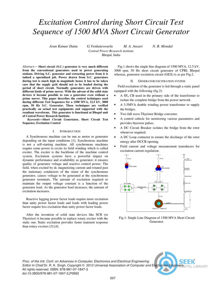
Fig.1 shows the single line diagram of 1500 MVA, 12.5 kV,
3000 rpm, 50 Hz short circuit generator of CPRI, Bhopal
whereas, generator excitation circuit (GEX) is as per Fig.2.
II.
GENERATOR EXCITRATION SYSTEM
Field excitation of the generator is fed through a static panel
equipped with the following (fig.2):
• A SF6 CB used in the primary side of the transformer to
isolate the complete bridge from the power network.
• A 5.5MVA double winding power transformer to supply
the bridges.
• Two full wave Thyristor Bridge converter.
• A control cubicle for monitoring various parameters and
provides thyristor pulses.
• A DC Circuit Breaker isolates the bridge from the rotor
whenever required.
• A DC Loop contactor to ensure the discharge of the rotor
energy after DCCB opening.
• Field current and voltage measurement transducers for
excitation current regulation.
Reactive lagging power factor loads require more excitation
than unity power factor loads and loads with leading power
factor require less excitation than unity power factor loads.
After the invention of solid state devices like SCR (or
Thyristor) it became possible to replace rotary exciter with the
static one. Static excitation provides faster transient response
than rotary exciters [3] [4].
Fig.1: Single Line Diagram of 1500 MVA Short Circuit
Generator.
Proc. of the Intl. Conf. on Advances in Computer, Electronics and Electrical Engineering
Editor In Chief Dr. R. K. Singh. Copyright © 2012 Universal Association of Computer and Electronics Engineers.
All rights reserved. ISBN: 978-981-07-1847-3
doi:10.3850/978-981-07-1847-3 P0692
207
Proc. of the Intl. Conf. on Advances in Computer, Electronics and Electrical Engineering
GEX ensures the following functions
• Regulation in Motor Mode
i.
Pulse Link operation
ii.
Synchronous operation
•
enough then the flux regulator is used, because flux is deduced
from voltage measurement.
IV.
To get the desired Short Circuit Voltage and Short Circuit
Current, Excitation control required in Generator Mode. Short
Circuit tests are conducted based on the rating and type of the
equipment. Various short circuit sequences are programmed
with the STP (Synchronous Test Processor).
Regulation in Generator Mode
i.
Stator voltage control
ii.
Flux control
iii.
Excitation current control during the short
circuit test sequences.
III.
REGULATION IN GENERATOR MODE
A. Short Time Duration S.C Sequences
To obtain short time duration tests (0-200 ms), the initial
stator voltage and ceiling ratio are preset to the desired values.
The short-circuit sequences are programmed in STP.
Fig.4 shows the excitation control block diagram during
short circuit test sequence. The generator output voltage and
current are continuously compared in a close loop cycle with
the preset reference values. The converters receive firing angle
of the thyristors from the controller, based on ceiling ratio and
comparator output [2].
REGULATION IN MOTOR MODE
A. Regulation in Pulse Link Mode
Initially machine is started as a synchronous motor. Position
of the rotor is determined by feeding excitation pulses from
the GEX panel. After sensing the rotor position, power at very
low frequency pulses from the Static Frequency Converter
(SFC) panel (Fig.1) is fed to stator winding in a precised
controlled manner. With this the rotor shifts from its stationary
position and tries to align with the stator magnetic axis. When
the next pulse is applied the stator magnetic axis shifts so as
rotor also. In this way rotor gets its rotation and its speed is
gradually increased with increase in frequency of stator pulses.
This starting method is called pulse link mode. In this mode
the stator supply frequency is stepped up from 0 to 2.5 Hz to
keep the rotor at 150 rpm.
B. Long Time Duration S.C Sequences
For these sequences the time duration is set by the STP is
in the range of 1sec to 3 sec. Other than setting the initial
stator voltage and ceiling ratio, in this case we also have to set
the short circuit current reference (SCR). The SCR is given in
long duration short circuit test to minimize the drop in the
current values at the end cycles due to armature reaction.
B. Regulation in Synchronous Mode
To take the machine up to rated speed i.e.3000 rpm the
frequency is increased gradually to 50 Hz that is the rated
speed. This is called synchronous mode operation. Fig-3
shows the Block Diagram of excitation during Motor mode. At
very low speed the exciter is only current regulated. When the
speed is increasing (so the back e.m.f.) and becomes high
Ref
+
Regulator
K.Is
Ref Ψ
PI
Mes I exc
+
Mes Ψ
Mes
Ψ>0.9
Mes
f>2 Hz
A
N
D
L
K.Is
(Allows to
reduce gain)
Ref
Uc
exc
Fig-3: Block Diagram of Excitation Control during
Motor mode.
Fig-2 Single Line Diagram of GEX.
208
Proc. of the Intl. Conf. on Advances in Computer, Electronics and Electrical Engineering
The system normally runs at rated speed in motor mode.
Conversion to the generator mode is done before drawing the
power from it. The steps for the mode conversion and short
circuit test are as follows:
• Blocking the pulses of SFC & GEX thyristors so that no
power is drawn from grid.
• Opening a circuit breaker between SFC output and stator
input to make physical isolation.
• Release the gate pulses of GEX thyristors so that field
power is fed to rotor according to the preset stator
reference voltage.
• As the machine was in full speed and disconnected from
the grid it will change to generator mode when it gets
rotor excitation.
• The generated output is fed to the test object through
certain protective and measuring devices.
C. Setting of sequence of operation in synchronous test
processor (STP) for a short circuit test – an example.
The following events are sequentially programmed (Table
1) in the STP during short circuit test:
Event No
01
02
03
04
05
06
07
08
09
10
11
12
After each operation, there is little drop in the speed. That
is recovered up by changing the mode from generator to motor
to attain 3000 rpm and it is ready for the next cycle of
operation.
Table 1 Sequence setting
Particulars to Start
Motor to Generator Mode
Excitation On
Master Circuit Breaker ON
Recording system ON
Protection Blocking Activated
Make Switch ON
S.C. Current Regulation ON
S.C. Current Regulation OFF
Master Breaker OFF
Excitation OFF
Protection Blocking Deactivated
Generator to Motor Mode
End of Sequence
The above sequences can be depicted as chronograms shown
in Fig.5.
G
Ie
Field
MB
Ref I
Ireg
PID
CT
Feed Back I
Ref V
O
R
Ø
Vreg
VT
Feed Back V
Fix
exc
Thyristor
Bridge
Fig.4: Block Diagram of Excitation Control during Generator
mode
Fig.5: Chronograms of SC Test sequence.
209
Proc. of the Intl. Conf. on Advances in Computer, Electronics and Electrical Engineering
V.
RESULTS
A. Motor Mode
The Fig.6 explains how the machine speeded up smoothly
to the reference speed with the help of SFC and controlled
field regulation in Pulse link mode as well as Synchronous
mode.
Fig.8. Long duration Test on CT.
n – rpm of synchronous machine
id – direct current in intermediate link
iu – phase current in winding U of
synchronous machine
Fig.6. Waveforms during Starting.
B. Generator Mode
In generator mode the regulator acts with a feedback from
stator current reference and actual stator current. The same is
represented in Fig.7.
Fig-7. Waveforms during Generator Mode.
Some of typical short circuit duty cycles performed using
this machine were recorded and shown in fig. 8 & 9.
210
Fig.9. Duty cycle on a Circuit Breaker.
Proc. of the Intl. Conf. on Advances in Computer, Electronics and Electrical Engineering
VI.
CONCLUSION
GEX control System plays a key role during short circuit
test sequence. It completely controls the desired value of stator
voltage and current by regulating the field excitation which is
shown exactly in the results. The GEX can also distinguish
between normal and abnormal condition with an alarm or a
trip signal.
ACKNOWLEDGMENT
The authors are thankful to the management of Central
Power Research Institute for giving the permission to present
the paper in the International Conference.
REFERENCES
[1]
[2]
[3]
[4]
B. V. Raghavaiah, N. R. Mondal, Arun Kumar Datta, Dr. Manisha
Dubey - Motor less operation of short circuit generator: a CPRI
perspective, ICEPES-2010.
Tsorng-Juu Liang, Jiann-Fuh Chen, Ching- Lung Chu, Kuen-Jyh
Chen, “Analysis of 12 Pulse Phase Control AC/DC Converter”, IEEE
1999 International Conference on Power Electronics and Drive
Systems, PEDS'99, July 1999, Hong Kong.
Jose R. Rodriguez, Jorge Pontt, Cesar Silva, Eduardo P. Wiechmann,
Peter W. Hammond, Frank W. Santucci, Roderigo Alvarez, Roderigo
Musalem, Samir Kouro and Pablo Lezana, “Large Current Rectifier:
State of the Art and Future Trends” IEEE Transactions on Industrial
Electronics, Vol. 52, No. 3, June 2005.
Akagi Hirofumi, “Large Static Converters for Industry and Utility
Applications” Proceedings of the IEEE, Vol. 89, No. 6, June 2001.
211


