Rear Spoiler_G sedan_K6030 1NFxx
advertisement
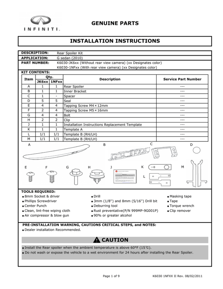
GENUINE PARTS INSTALLATION INSTRUCTIONS DESCRIPTION: APPLICATION: PART NUMBER: Rear Spoiler Kit G sedan (2010) K6030-JK6xx (Without rear view camera) (xx Designates color) K6030-1NFxx (With rear view camera) (xx Designates color) KIT CONTENTS: Qty. Item JK6xx 1NFxx 1 A 1 1 B 1 C 1 5 D 5 4 E 4 F 2 4 G 4 4 H 2 2 1 1 J 1 K 1 1/1 1/1 L M 1/1 1/1 Description ------------------------- Rear Spoiler Inner Bracket Spacer Seal Tapping Screw M4×12mm Tapping Screw M5×16mm Bolt Clip Installation Instructions Replacement Template Template A Template B (RH/LH) Template B (RH/LH) A E Service Part Number C B F G H J D K M L TOOLS REQUIRED: ● 8mm Socket & driver ● Phillips Screwdriver ● Center Punch ● Clean, lint-free wiping cloth ● Air compressor & blow gun Drill 3mm (1/8'') and 8mm (5/16'') Drill bit ● Deburring tool ● Rust preventative(P/N 999MP-9G001P) ● 90% or greater alcohol Masking tape Tape ● Torque wrench ● Clip remover ● ● ● ● PRE-INSTALLATION WARNING, CAUTIONS CRITICAL STEPS, and NOTES: Dealer installation Recommended. ● CAUTION ● ● Install the Rear spoiler when the ambient temperature is above 60°F (15 ℃). Do not wash or expose the vehicle to a wet environment for 24 hours after installing the Rear Spoiler. Page 1 of 9 K6030 1NFXX II Rev. 08/02/2011 INSTALLATION PROCEDURE: Fig 1-1 1) 2) Disconnect vehicle battery (negative terminal). Open vehicle trunk lid and find trunk lid bumper assemblies (RH/LH: 1 location each) Fig 1-2 3) Use a small ruler to measure the gap between bottom of trunk lid bumper assembly and top of trunk lid bumper nut (RH/LH 1 location each). Write down measured dimensions in following table. Trunk lid Trunk lid bumper assembly Trunk lid trim Measurement this gap Trunk lid bumper Check gap. Trunk lid bumper gap See Fig.9-6. RH Trunk lid bumper assembly LH Trunk lid bumper nut mm Fig 2 Wrapping foam 4) 5) Tape mm Remove rear spoiler A from box, unwrap it, and put it back in box until later in the procedure. Attach wrapping foam from rear spoiler A to trunk opening with tape. NOTE: After removing wrapping foam from rear spoiler, be sure not to scratch the part. Be sure to cover the trunk striker with the drop cloth. Trunk striker Trunk lid bumper assembly (2 locations; reuse) Fig 3 6) Trunk handle (reuse) 7) Remove inner trim clips (9 locations; reuse), trunk lid bumper assembly (2 locations; reuse), trunk handle (reuse) and emergency release (reuse) from trunk lid with a clip remover. Remove inner trim from trunk lid. Clips (9 locations; reuse) Inner trim Emergency release (reuse) Page 2 of 9 K6030 1NFXX II Rev. 08/02/2011 INSTALLATION PROCEDURE: 8) Disconnect trunk lid opener switch connector and rear view camera connector (if vehicle is equipped with rear view camera), and remove their grommets. 9) If ground wire exists, remove bolt that attaches it to trunk lid. 10) Remove nuts that attach chrome trunk lid finisher (4 locations). Fig 4-1 Grommet (1 or 2 locations) Ground wire Connector (1 or 2 locations) Chrome trunk lid finisher nuts (4 locations) 11) Apply masking tape around chrome trunk lid finisher to prevent scratches. 12) Using clip remover, disengage clips (RH and LH) and remove chrome trunk lid finisher. Fig 4-2 Masking tape Clip remover Check gap. Clip (hidden) See Fig.9-6. Chrome trunk lid finisher 13) If vehicle is not equipped with rear view camera, remove grommet. Fig 4-3 Grommet (reuse) Fig 5-1 Screws (discard) Screws (discard) Inner bracket (discard) Rear view camera (reuse) Inner bracket (discard) Screws (discard) If vehicle has rear view camera 14) Remove Screws (4 locations) that attach inner bracket, and remove inner bracket from chrome trunk lid finisher. 15) Remove Screws (4 locations) that attach rear view camera and trunk opener switch to innner bracket. NOTE; Be careful not to lose rear view camera and trunk opener switch. They will be used again. Trunk opener switch (reuse) Page 3 of 9 K6030 1NFXX II Rev. 08/02/2011 INSTALLATION PROCEDURE: Screws (discard) Inner bracket (discard) If vehicle doesn't have rear view camera 16) Remove screws (4 locations) that attached inner bracket, and remove inner bracket from chrome trunk lid finisher. 17) Remove screws (2 locations) that attach trunk opener switch to inner bracket. NOTE; Be careful not to lose trunk opener switch. They will be used again. Fig 5-2 Screws (discard) Trunk opener switch (reuse) 18) Align template A to trunk lid and apply masking tape to hold template in place. 19) Mark hole position (+) with senter punch. 20) Remove masking tape and template A. Fig 6-1 Template A Check gap. Masking tape Masking tape See Fig.9-6. Mark with center punch Align to edge of holes Fig 6-2 Template B Masking tape Mark with center punch Masking tape Align to edge of holes Fig 6-3 Template C Align to edge of trunk lid Mark with center punch 21) Align template B (LH) to trunk lid and apply masking tape to hold template in place. 22) Mark hole position (+) with senter punch. 23) Remove masking tape and template B (LH). 24) Repeat procedures 21) through 23) using template B (RH) for right hand side installation. Template C 25) Fold tabs of template C (LH). 26) Align template C (LH) to trunk lid and apply masking tape to hold template in place. 27) Mark hole position (+) with senter punch. Fold Trunk lid Cross-section B-B Page 4 of 9 K6030 1NFXX II Rev. 08/02/2011 INSTALLATION PROCEDURE: 28) Remove small portion of template C (LH) by tearing template C at slit. 29) Repeat procedures 25) through 28) using template C (RH) for right hand side installation. Fig 6-4 Template C Slit Peel up Small portion of template C Approx. 10mm Fig 7-1 Drill bit Masking tape Check gap. Drill 3mm→8mm (1/8"→5/16") See Fig.9-6. Fig 7-2 Trunk lid 30) Wrap masking tape around 3mm (1/8") and 8mm (5/16") drill bits, approximately 10mm from tip. 31) Drill 1/8" (3mm) → 5/16" (8mm) holes at 5 marked locations on trunk lid. 32) Remove any sharp edges from drilled holes with deburring tool and remove metal shavings from inside trunk lid with air compressor and blowgun. 33) Apply rust preventative (P/N 000MP 9G001P) to drilled holes. 34) Using a clean, lint free cloth and 90% or greater alcohol, wipe any dirt and oil from around holes where seals D will be applied. Let area dry thoroughly. 35) Attach seals D to trunk lid (5 locations). Seal D Fig 8-1 Tapping screw F Rear view camera inner bracket B Tapping screw F Trunk opener switch If vehicle has rear view camera 36) Route trunk lid opener switch grommet through inner bracket B hole. 37) Assemble trunk lid opener switch to inner bracket B by installing tapping screw M5×16mm F. NOTE; Tightening torque; 2.1 to 2.5 N m (18.6 to 22.1 lbf in) 38) Loosely assemble rear view camera to inner bracket B by installing tapping screw M5×16mm F. Trunk lid grommet With rear view camera Page 5 of 9 K6030 1NFXX II Rev. 08/02/2011 INSTALLATION PROCEDURE: Tapping screw E Inner bracket B Trunk lid Rear spoiler A opener switch Fig 8-2 Rear view camera Consistent gap Tapping screw F Fig 8-3 Trunk lid Check gap. See Fig.9-6. opener switch Spacer C Inner bracket B Without rear view camera Fig 8-4 Tapping screw E Inner bracket B Rear spoiler A 39) Loosely assemble inner bracket B to rear spoiler A by installing tapping screw M4×12mm E 40) Adjust inner bracket until there is consistent gap between rear spoiler A opening and trunk lid opener switch. Tighten inner bracket with tapping screw E. Adjust rear view camera until there is consistent gap between rear spoiler A opening and rear view camera. Tighten rear view camera with tapping screw F. NOTE; Rear view camera tightening torque; 2.1 to 2.5 N m (18.6 to 22.1 lbf in) Inner bracket tightening torque; 0.8 to 1.0 N m (7.1 to 8.8 lbf in) If vehicle doesn't have rear view camera 41) Route trunk lid opener switch grommet through inner bracket B hole and spacer C. 42) Assemble trunk lid opener switch to inner bracket B by installing tapping screw M5×16mm F through spacer C. NOTE; Tightening torque; 2.1 to 2.5 N m (18.6 to 22.1 lbf in) 43) Loosely assemble inner bracket B to rear spoiler A by installing tapping screw M4×12mm E 44) Align center of switch to center of rear spoiler A hole then tighten inner bracket B. NOTE; Tightening torque; 0.8 to 1.0 N m (7.1 to 8.8 lbf in) Rear spoiler A Trunk lid opener switch Consistent gap Fig 8-5 45) Assemble clips H to rear spoiler A. Clip H Rear spoiler A Page 6 of 9 K6030 1NFXX II Rev. 08/02/2011 INSTALLATION PROCEDURE: Behind Outside Fig 8-6 46) Remove approximately 20mm of tape liner from double-sided tape on rear spoiler A in direction shown by arrow. 47) Fold tape liner pull tabs onto rear spoiler surface and apply masking tape to ensure that pull tabs are accessible. Fig 8-7 48) Using a clean, lint free cloth and 90% or greater alcohol, wipe any dirt and oil from mounting surface. Let area dry thoroughly. 49) If vehicle is not equipped with rear view camera install grommet that was removed in 13). Fig 9-1 50) Pull rear view camera and trunk lid opener switch grommets through trunk lid holes. 51) Align rear spoiler A on trunk lid and engaged rear spoiler A clips H. Rear spoiler A Tape liner Masking tape Cleaning area Check gap. Grommet See Fig.9-6. Clips H Rear spoiler A Rear view camera grommet hole Holes Trunk lid opener switch hole Fig 9-2 52) Loosely install rear spoiler A with bolt G from inside of trunk lid. 53) Connect trunk lid opener switch connector and rear view camera cnnector (if vehicle is equipped with rear view camera) which are disconnected in 8). 54) Connect vehicle battery (negative terminal). 55) Confirm operation of trunk lid opener switch and rear view camera. 56) Disconnect vehicle battery (negative terminal). Bolt G Page 7 of 9 K6030 1NFXX II Rev. 08/02/2011 INSTALLATION PROCEDURE: 57) Position rear spoiler A equality clearance from aligning line of template C RH and LH. Fig 9-3 View A View B Rear spoiler A Template C LH Template C RH LH RH View A Check gap. View B Fig 9-4 58) Remove tape liner "a" in direction shown by arrow, push forward and apply 15lbs. of pressure 3 times on rear spoiler A from center to outward. 59) Remove tape liner in direction shown by arrow, push downward and apply 15lbs. of pressure 3 times on rear spoiler A in order: b-c. 60) Remove masking tape and template C RH/LH. 61) Tighten bolt G that were loosely installed in 52). 62) Connect trunk lid opener switch, rear view camera switch, and attach ground wire that were removed in 8) and 9). 63) Reinstall all parts that were labeled reuse, using reverse of removal process. Fig 9-5 64) Adjust trunk lid bumper assembly by turning trunk lid bumper nut clockwise until gap between bottom of trunk lid bumper and top of trunk lid bumper nut matches gap measured in 3). 65) Remove wrapping foam and close trunk lid. 66) Connect vehicle battery (nagative terminal). See Fig.9-6. Push Push Measurement this gap Trunk lid bumper Rear view camera-equipped vehicle Trunk lid bumper assembly Trunk lid bumper nut CAUTION After completely installing vehicle parts, make sure to do rear view camera calibration. Page 8 of 9 K6030 1NFXX II Rev. 08/02/2011 INSTALLATION PROCEDURE: Fig.9-6 Rear spoiler A d a b c Limit gap X mm a b c d 1.0 1.5 1.0 1.5 ACCESSORY CHECK: Please check that installation has no problem. Check gap. See Fig.9-6. REINSTALLATION OF REMOVED PARTS Re-install all removed vehicle parts. Refer to the vehicle service manual for more details. Clean trunk opening of vehicle. FINAL INSPECTION: Verify re-installed trim parts for proper flush fit Verify all clips are fully engaged and locked. Verify re-installed trim parts are free from cracks, scratches or stress marks. VEHICLE CHECK Remove all tools from vehicle. Page 9 of 9 K6030 1NFXX II Rev. 08/02/2011
